8 operating configuration, Table 2-9. internal jumper configuration, 9 status port – KEPCO BHK-MG 200W (Full Rack) Series User Manual
Page 43: Operating configuration -13, Status port -13, Internal jumper configuration -13
BHK-MG (OPR) 022014
2-13/(2-14 Blank)
2.8
OPERATING CONFIGURATION
The complete operating configuration is defined by jumper configuration of internal boards.
Table 2-9 lists the location of the internal jumpers and their function. This information is provided
for reference purposes only, to indicate the configuration options available. Do not attempt to
alter the jumper configuration. For assistance in changing any jumper-selected parameter con-
tact Kepco Applications Engineering.
2.9
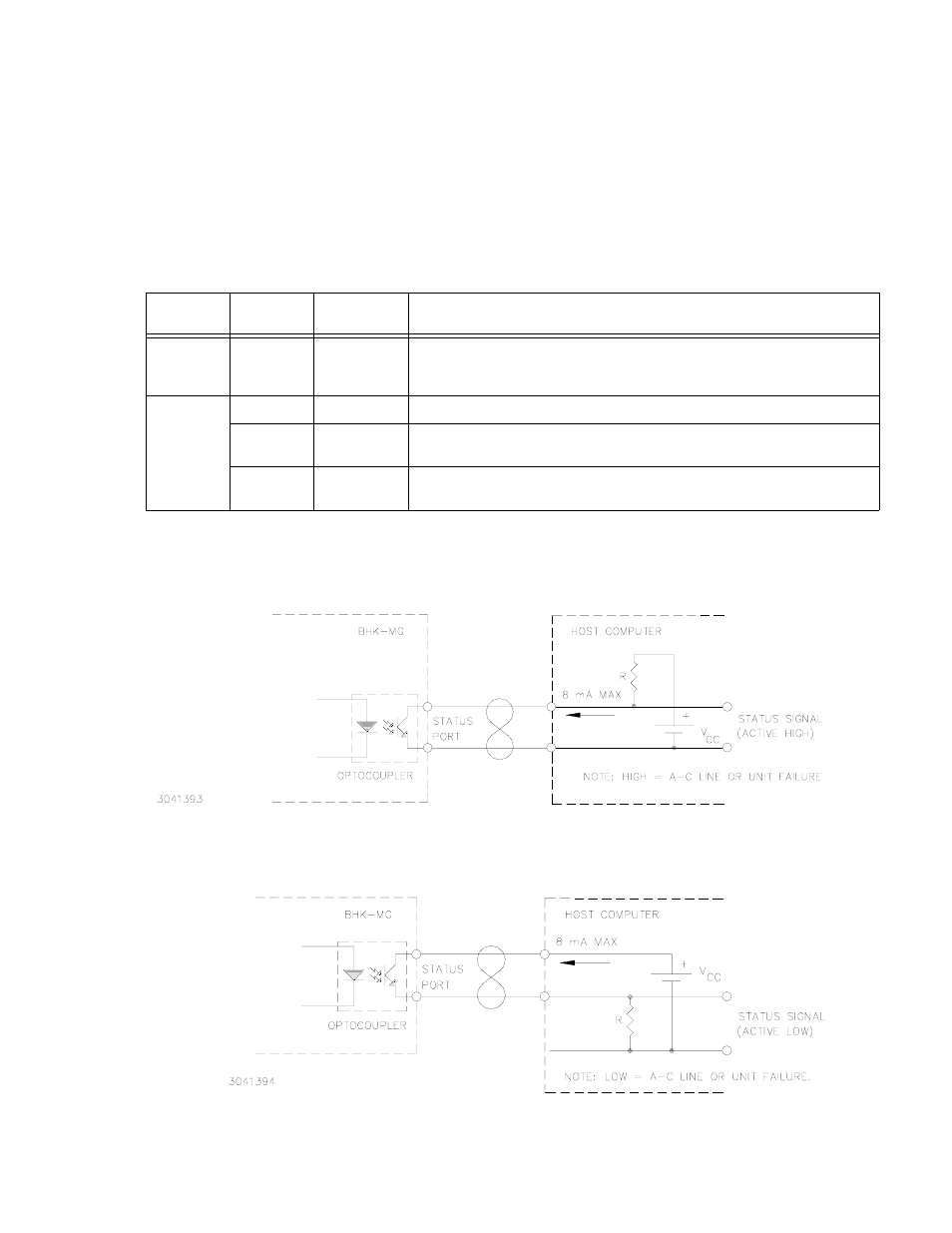
STATUS PORT
The status port opto-coupler can be configured for either active “high” (see Figure 2-6) or active
“low” (see Figure 2-7).
FIGURE 2-6. STATUS PORT OPTO-COUPLER ACTIVE “HIGH” CONFIGURATION
FIGURE 2-7. STATUS PORT OPTO-COUPLER ACTIVE “LOW” CONFIGURATION
TABLE 2-9. INTERNAL JUMPER CONFIGURATION
LOCATION
JUMPER
DEFAULT
STATUS
FUNCTION
A1
J6
Not Installed
May be installed temporarily to force the unit to enter First Time Calibration during
power-up sequence. This requires the operator to enter the model and perform a
full calibration of the unit.
A7
J12
Installed
Enables input circuit breaker to trip when input power loss detected.
J13
Installed
Enables protection circuit to cut off pass element and to send a flag to digital con-
trol.
J14
Installed
Enables “share circuit” to act on protection circuit. The share circuit detects uneven
voltage or current across the pass element.