Jenway 3540 User Manual
Page 72
8.60
Functional Check – Conductivity
A simple but effective method for checking the conductivity channel can be made with
two 10K ohm resistors. One for checking the ATC function and the two together for
checking the conductivity function.
Disconnect all probes and connectors from the 3540 except for the power supply jack
plug. The Temperature display below the conductivity reading should indicate 25.0
o
C
M (or any other temperature that has been entered as the manual temperature
compensation value in the conductivity temperature set up menu see section 4.42)
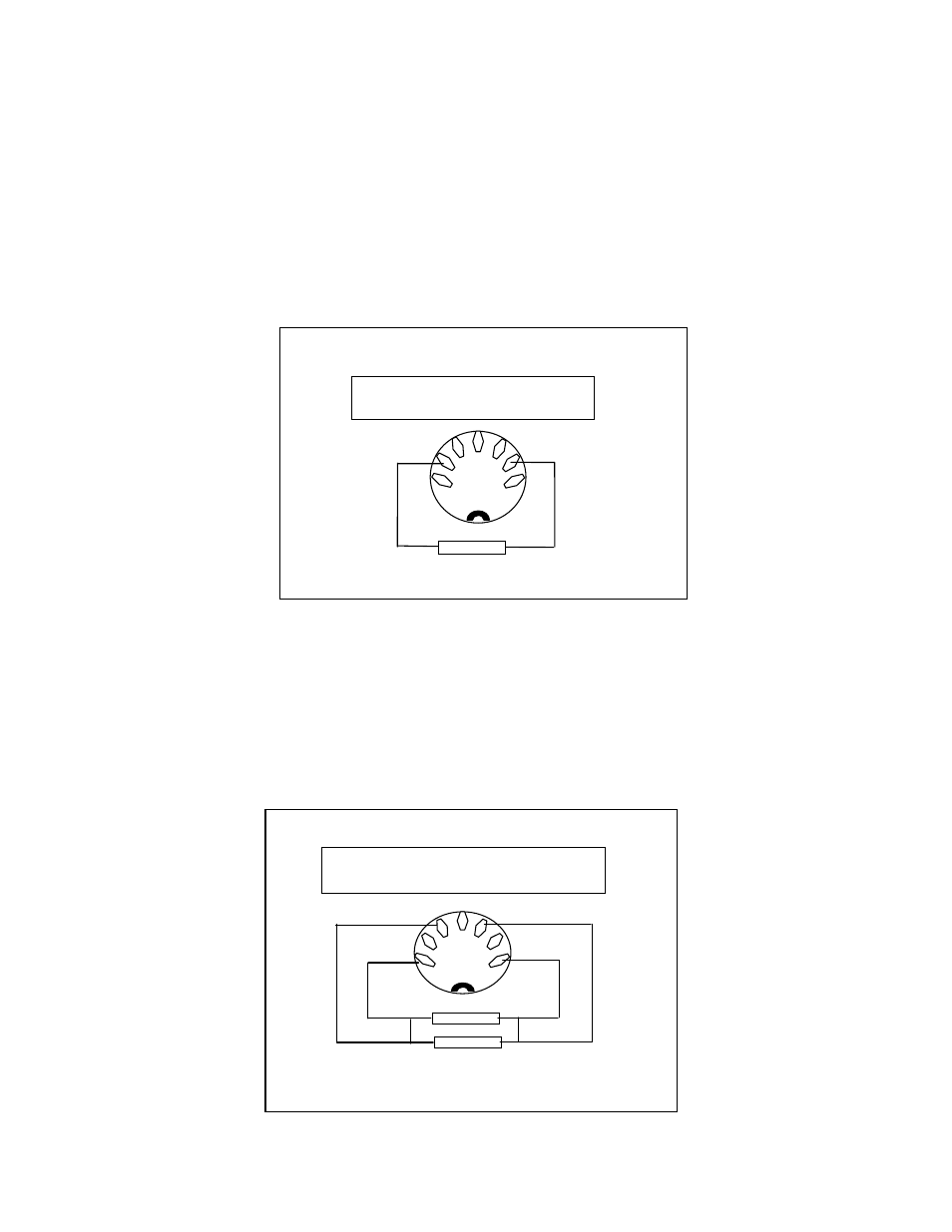
Insert the leads of a 10K ohm resistor in the sockets of the conductivity probe
connector on the rear panel as shown below. The conductivity temperature display
should now read between 24 and 26
o
C without the M symbol – indicating that the
resistor has been detected as an ATC sensor. If this functions correctly then any
problem is most likely to be associated with the probe – if it fails to work correctly
contact your local distributor or Jenway for service advice.
To check the conductivity function, remove the resistor from the socket, lay it
alongside the other resistor. Link the pairs of leads close to the resistor body, by
twisting or soldering to form a parallel combination as shown in the diagram. Keep the
four ends of the leads separate, as these represent the four-wire connection of the
conductivity probe. Insert these four wires into the conductivity socket as shown. The
Two 10K ohm
Resistors in
parallel
Conductivity Probe Socket viewed from rear
panel
10K ohm Resistor
Conductivity Probe connector viewed
from rear panel
Checking ATC/Temperature Function