Jenway 3540 User Manual
Page 5
1.2
Display and Controls
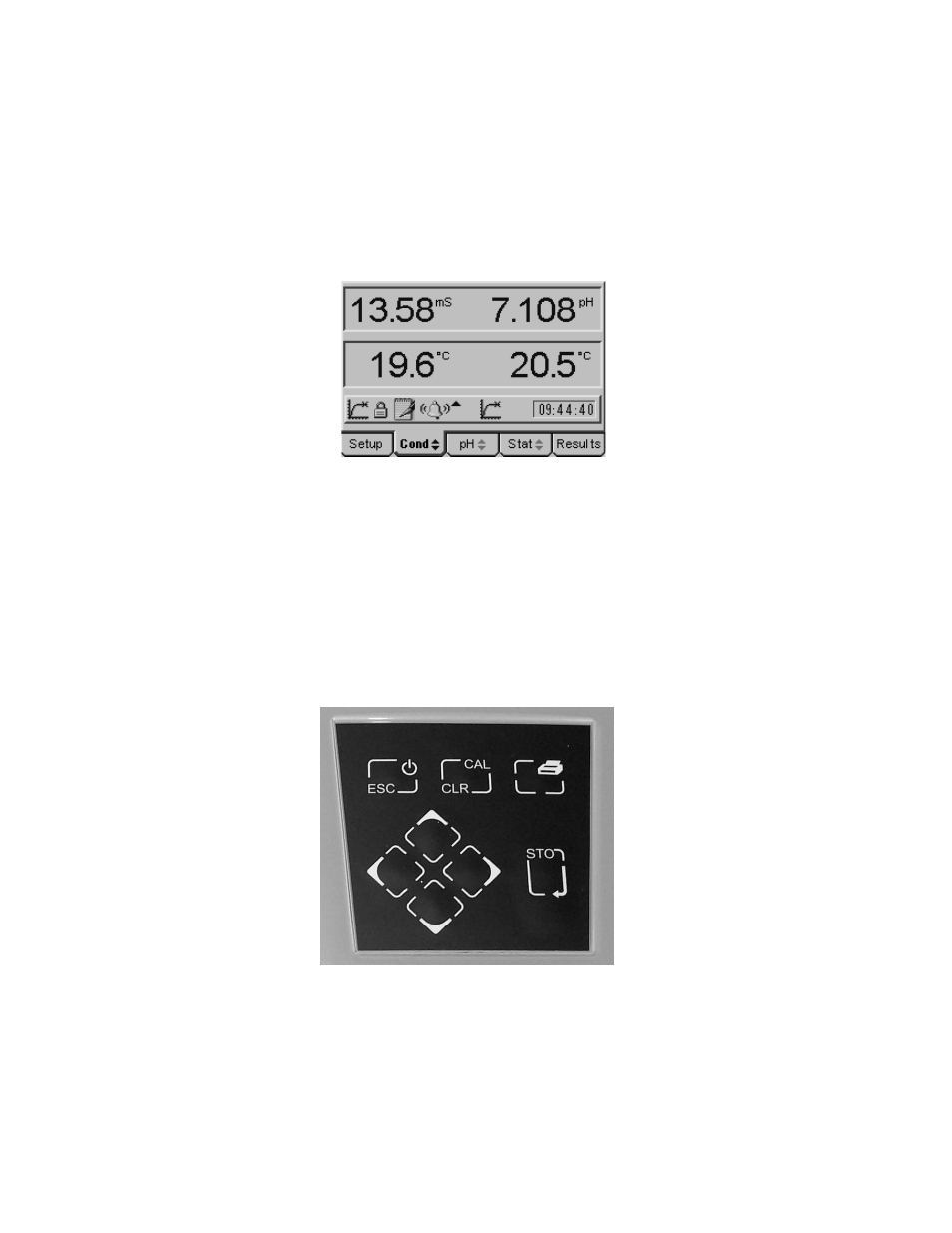
The model 3540 has a back lit 1/8 VGA dot matrix LCD. In normal measurement mode the
left-hand side displays the conductivity value and the right hand side the pH value. Both
channels have their own temperature/ATC input displayed below the measured value,
making them fully independent. The display includes a number of icons and prompts used to
inform and indicate to the user the instrument status and measurement conditions. The
operating system is based around five separate screens, each of which can be displayed by
moving the cursor along the tabbed menu bar at the bottom of the display.
Typical display showing independent temperature/ATC
measurement and a range of prompting icons
The simple keypad controls all the functions of the instrument. The ON/OFF key operates as
an escape [ESC] key at sub-menu levels, each press returning to the next highest level until
the main measurement screen is reached, where a further press will switch the instrument
off.
Pressing the CAL key initiates the calibration sequence for the channel highlighted on the
tabbed menu bar. The calibration sequence will be based on the options selected in the
relevant calibration set up menu. When recalling results, with the Results tab highlighted, the
CAL key functions as a Clear [CLR] key, returning the function defined for the Clear key in
the data logging set up menu.
Simple keypad enables easy operation
The Print key outputs the currently displayed measurement, stored results or statistics
screen to the RS232 serial port, where it can be printed on the optional serial printer. An
option to print the measurement displayed on one or both channels can be selected in the
Printer Set Up menu.