GW Instek PSM-Series User Manual User Manual
Page 6
PSM-SERIES PROGRAMMABLE POWER SUPPLY
USER MANUAL
⎯ ⎯
5
Specification
PSM-2010
PSM-3004
PSM-6003
Voltage
0.02% + 1mV
Current
0.1% + 1mA
Memory
Store/Recall points 0~99
Temperature Coefficient per ℃±(% of output + offset) : Maximum change in output
/ readback per ℃ after 30-minute warm-up.
Voltage
0.01% + 3mV
Current
0.02% + 3mA
AC Input
100VAC, 120VAC, 220VAC ±10%,
230VAC, –6%+10%, 50/60Hz
Input Rating
700VA, 380W
300VA, 220W
600VA, 310W
Interface
RS-232, GPIB
Accessories (1)
Power cord ×1, Instruction manual×1,
Programmer Manual×1
Type
Item
Common terminal
CE Safety
terminal
Test Lead
1
1 set
Sense Lead
0
1 set
Grounding Lead
0
1
Short bar A
on Front panel
3
0
Accessories (2)
Short bar B
on Rear panel
3
3
Operation
Environmental
Indoor use
Altitude up to 2000 m
Ambient temperature:
To satisfy specifications : 10℃~ 35℃( 50
° F ~ 95°F )
Maximum operating ranges: 0℃~ 40℃( 32
°F ~ 104°F )
Relative humidity: 85% RH (max.) non condensing
Pollution degree: 2
Storage Temperature &
Humidity
-10℃to 70℃, 70%RH (maximum)
Dimensions & Weight
230(W)×140(H)×380(L) mm. Approx. 10kg.
PSM-SERIES PROGRAMMABLE POWER SUPPLY
USER MANUAL
⎯ ⎯
6
3. PRECAUTIONS BEFORE OPERATION
3-1. Unpacking the Instrument
The product has been fully inspected and tested before shipping from the factory.
Upon receiving the instrument, please unpack and inspect it to check if there is
any damage caused during transportation. If any sign of damage is found, notify
the bearer and/or the dealer immediately.
3-2. Checking the Line Voltage
The product can be applied by any kind of line voltages shown in the table below.
Before connecting the power plug to an AC line outlet, make sure the voltage
selector of the rear panel is set to the correct position corresponding to the line
voltage. It might be damaged the instrument by connecting to the wrong AC line
voltage.
WARNING. To avoid electrical shock the power cord protective
grounding conductor must be connected to ground.
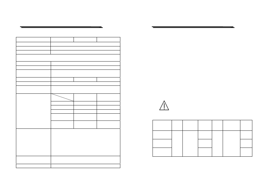
When line voltages are changed, replace the required fuses shown as below:
Model
Line
voltage
Range
Fuse
Line
voltage
Range
Fuse
PSM-2010
T 7A
250V
T3.15A
250V
PSM-3004
T3.15A
250V
T 1.6A
250V
PSM-6003
100V
120V
90-110V
108-132V
T 5A
250V
220V
230V
198-242V
216-250V
T2.5A
250V