The system diagram and description – GW Instek PSM-Series User Manual User Manual
Page 31
PSM-SERIES PROGRAMMABLE POWER SUPPLY
USER MANUAL
⎯ ⎯
55
7. THE SYSTEM DIAGRAM AND DESCRIPTION
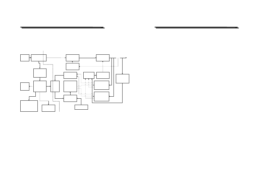
7-1. Block Diagram
The graph above is the system diagram of PSM-SERIES, which consists of
Micro Processor Unit (MPU), Digital to Analog Converter (DAC), Analog
Switch Circuit, Reference Voltage Circuit, Driver Circuit, Control Circuit,
Comparator, Phase Control and etc.
AC
INPUT
TRANSFORMER
PRE_
REGULATOR
VOLTAGE
COMPARATOR
CURRENT
COMPARATOR
D TO A
CONVERTER
REFERENCE
ANALOG
SWITCH
AND SAMPLE
HOLD
MICRO
CONTROL
VFD
DISPLAY
KEYBOARD
AUX
RECTIFIER
AND FILTER
SERIES
REGULATOR
AMPLIFIER
OR
GATE
O/P
INTERFACE
RS-232 OR GPIB
PHASE
CONTROL
PROTECTION
CIRCUIT
A TO D
CONVERTER
OPTO-
COUPLE
R
PSM-SERIES PROGRAMMABLE POWER SUPPLY
USER MANUAL
⎯ ⎯
56
7-2. The Configuration of Block System
The whole Block system consists of two Circuit Blocks, Digital Control
circuit (connected to the ground) and power output circuit (isolated from
the ground):
Digital Control circuit: MPU (Micro Processor Unit), VFD DISPLAY,
Interface Control Card, GPIB (IEEE-488) and RS-232.
Power output circuit: DAC (Digital to Analog Converter), ADC (Analog
to Digital Converter), Analog Switch Circuit, Reference
Voltage Circuit, Driver Circuit, Control Circuit,
Comparator and Phase Control.
The MPU is the heart of PSM-SERIES control the DAC(digital to analog
converter) control to provide the required reference voltage source of
voltage, current, Over Voltage protection, Over Current protection in order
to make the accurate setting and protection. Then, use the reference
voltage to control the Analog Switch Circuit to achieve high quality and
high accuracy output. Beside, the protection precaution detected by the
hardware can reach speedy and accurate purpose.