Additel 221A Multifunction Temperature Calibrator User Manual User Manual
Page 81
________________________________________________________________________________________________________________
74
11.4.3 PV Calibration
Adjust the HART transmitter’s PV LRV and URV to get the coherence
between the standard source range and digital analog output (AO). To
perform the PV Calibration operation, proceed as follows:
1. In the HART diagnostic and service interface, choose PV Calibration
from list, then pressEnteror Select to show the PV Calibration Setting
Interface (Figure 11.9).
2. In the SettingInterface, you can set the sensor type and the range of
the transmitter. If the device is a pressure transmitter, the pressure
module has to be connected to the calibrator and pressure controller
such as hand pump is also available for this application. Note: the
UUT’s input pressure unitshould match the previousUnit. The unit of
pressure will be automatically selected by the calibrator.
3. Press Enter or Done to view the PV CalibrationProcess interface
(Figure 11.10). Note that the calibrator will judge whether these
input values are available for the transmitter before starting the PV
Calibration Process.
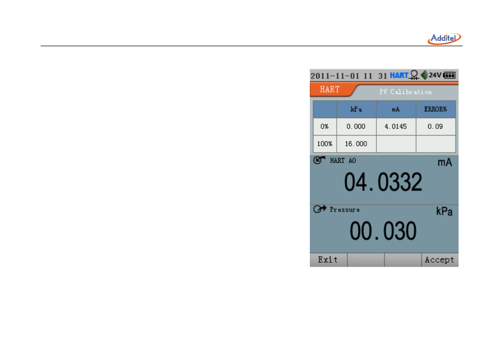
4. The PV calibration process allows you to calibrate the Lower (0%)
and Upper (100%) Range Values (LRV and URV) have been previously
set in PV Calibration Setting interface. Located at the top of the PV Calibration interface is the error summary table
Figure 11.10 HART PV Calibration Process