Installation – Lincoln Electric IM866 POWER REAM User Manual
Page 9
INSTALLATION
- 9 -
POWER REAM
G
G
Clamp
Open
Closed
Lift
Top
Bottom
R
R
G
G
Y
Y
R
R
G
R
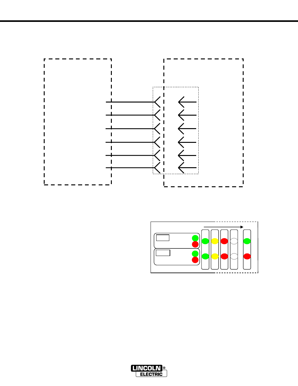
Power Ream to Lincoln Electric Welding Robot Cell
*These labels are for reference only.
Power Up Sequence
: Once the unit is wired into
the robot and power is applied the LEDs will
display the power up sequence (green – yellow –
red) and then show positions of the cylinders
according to the legend next to the LED window.
If the LEDs are not reporting the clamp open and
the lift at the bottom then check the air pressure or
position sensors. If the LEDs are flashing red or
green check for start lock (see below). If the LEDs
are flashing yellow ensure the setup pushbutton is
not pressed or defective.
Start Lock:
The start lock feature guards against a start signal present when the unit is powered up. If a
start signal is present, the POWER REAM will not cycle immediately after powering up. The LEDs will
display the power up sequence (green-yellow-red) and then flash green / red if an output from the robot is
present.
Robot Input:
With the clamp open and the lift at the bottom, the ―complete‖ input to the robot will be on.
If it is not, the robot input type may need to be configured.
Robot Output:
If by forcing on the ―Start‖ or ―Spray‖ output from the robot no action occurs, the robot
output type may need to be configured.
WELDING
ROBOT CELL
WIRES IN
CONTROL PANEL
0V
+24V
*DI-3
*DO-3
*DO-4
*DI-4
POWER REAM
K2391-1 or similar
equipment
1
0V
2
+24V
3
Complete
4
Start
5
Spray
6
Error
2 WHITE
1 or 27 RED
4 GREEN
3 ORANGE
5 BLACK
6 BLUE