Pneumatic diagram - 29 – Lincoln Electric IM866 POWER REAM User Manual
Page 29
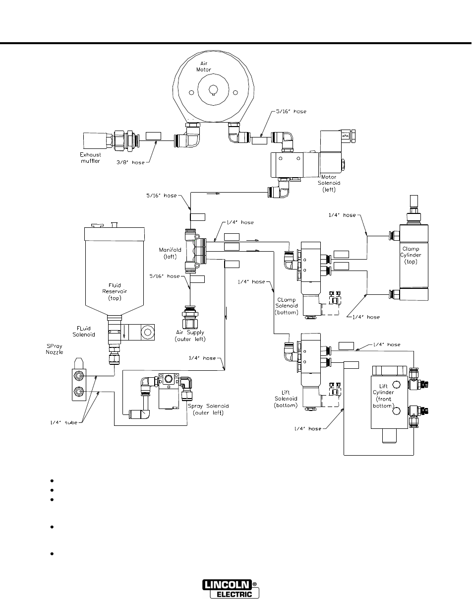
PNEUMATIC DIAGRAM
- 29 -
POWER REAM
112
R1
P
B
A
R2
R2
A
P
R1
B
111
110
100
120
130
140
121
122
131
132
Note: All locations are referenced from the back of the unit
Additional pneumatic troubleshooting information:
Air enters the unit through hose 100 and is distributed to the solenoids through the manifold
Hose 110 feeds the motor solenoid. Air flows through hose 111 and 112 when the motor is on.
Hose 120 feeds the clamp solenoid. Hose 121 is normally pressurized, keeping the clamp in the open
position. When the clamp is closed hose 122 become pressurized. Air flows through lines 121, 122,
and out the breather vents of the clamp solenoid when opening or closing.
Hose 130 feeds the lift solenoid. Hose 131 is normally pressurized, keeping the lift in the bottom
position. When the lift is raised hose 132 becomes pressurized. Air flows through lines 131, 132, and
out the breather vents of the lift solenoid when raising or lowering
Hose 140 feeds the spray solenoid. Air flows through the tubing when the sprayer is on.
- Invertec V310-T DC (2 pages)
- VANTAGE 500 (CE) 11575 (50 pages)
- INVERTEC V350-PRO SVM152-A (155 pages)
- IMVERTEC V160-T (36 pages)
- IDEALARC CV-300 (112 pages)
- INVERTEC POWER WAVE 450 SVM112-B (293 pages)
- AUTO-DARKENING HELMET IM10001 (12 pages)
- IM10111 IDEALARC R3R-500-I (28 pages)
- IM10110 IDEALARC R3R-400 (25 pages)
- IM10051 INVERTEC V311-T AC_DC (38 pages)
- IM10059 SQUARE WAVE TIG 175 (30 pages)
- IM10096 POWER MIG 256 (37 pages)
- IM10096 POWER MIG 256 (38 pages)
- IM10105 POWER MIG 350MP (47 pages)
- IM10115 FLEXTEC 650 (42 pages)
- IM10132 FLEXTEC 650 (56 pages)
- IM10132 FLEXTEC 650 (36 pages)
- IM10018 IDEALARC DC-600 VRD (55 pages)
- IM10107 IDEALARC DC-400 (40 pages)
- IM10062 FLEXTEC 450 (72 pages)
- IM10091 FLEXTEC 450 CE (40 pages)
- IM10094 RED-D-ARC FX450 (31 pages)
- IM10157 12_24V 10A Auto HF Household Charger (16 pages)
- IM10139 JUMP STARTER (12 pages)
- IM10149 POWER WAVE ADVANCED MODULE (46 pages)
- IM10102 AIR VANTAGE 650 (60 pages)
- IM10103 AIR VANTAGE 700 (AU) (57 pages)
- IM10065 AIR VANTAGE 500 CUMMINS (54 pages)
- IM10066 AIR VANTAGE 500 (AU) (56 pages)
- IM10041 VANTAGE 500 CUMMINS (56 pages)
- IM10128 AIR VANTAGE 500 KUBOTA (AU) (56 pages)
- IM10090 ARC TRACKER (48 pages)
- IM10147 AUTO-DARKENING HELMET (12 pages)
- IM10087 AutoDrive 19 CONTROLLER (28 pages)
- IM10125 AutoDrive 19 TANDEM (34 pages)
- IM10069 AutoDrive 4R100 (32 pages)
- IM10145 AUTOPRO 20 (24 pages)
- IM10025 BIG RED 500 (40 pages)
- IM10019 BIG RED 600 (41 pages)
- IM10005 BULLDOG 140 (46 pages)
- IM10074 BULLDOG 5500 (56 pages)
- IM10067 CENTURY AC120 (20 pages)
- IM10109 CIRCULATOR (36 pages)
- IM10109 CIRCULATOR (33 pages)
- IM10153 CLASSIC 300 HE (60 pages)