Operation - 15 – Lincoln Electric IM866 POWER REAM User Manual
Page 15
OPERATION
- 15 -
POWER REAM
Operation
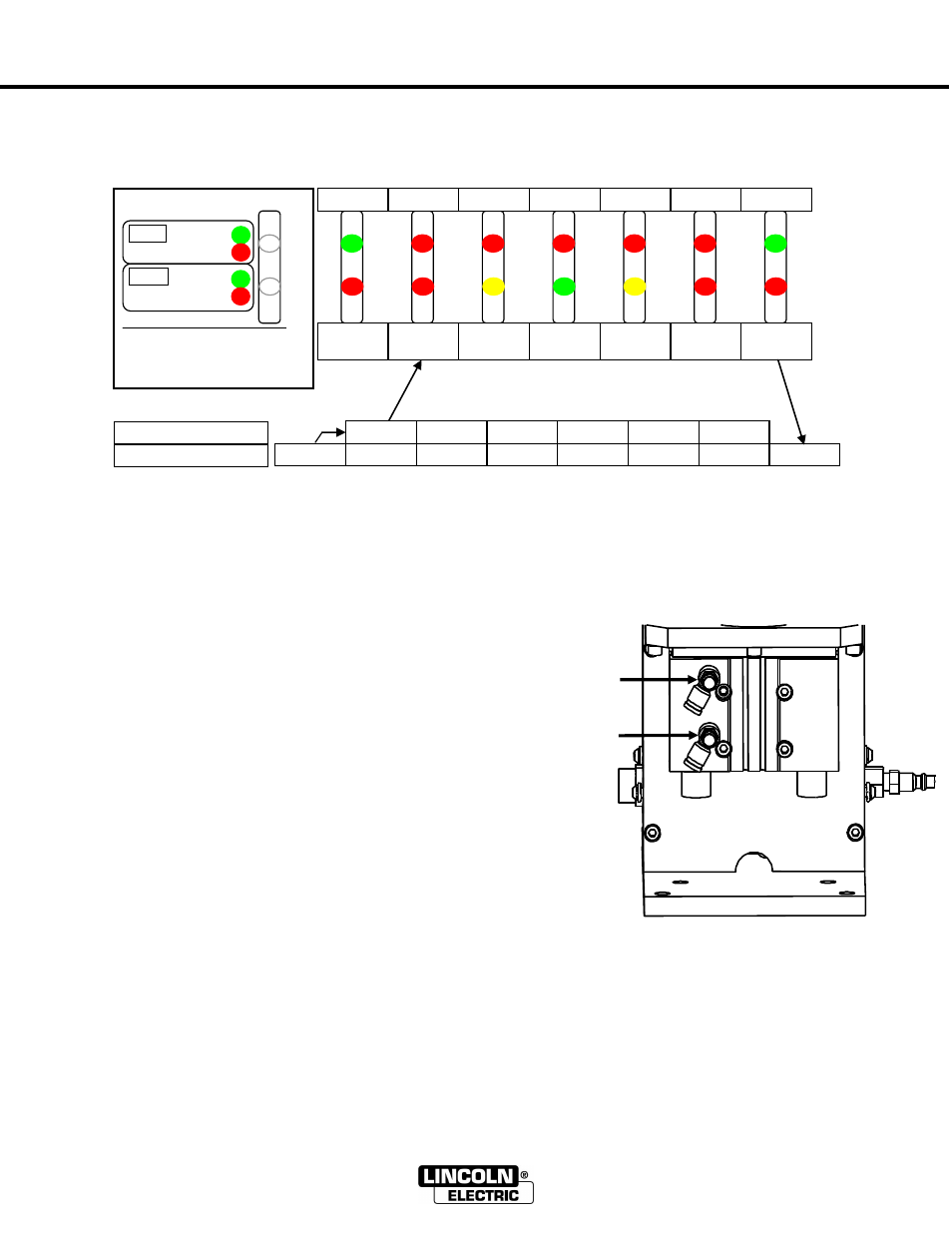
The following diagram shows the 7-step reaming sequence and color of the indicator lights at each stage.
The indicator lights show the position of the clamp and lift cylinders on the user interface.
The above diagram shows the robot input and output as the sequence progresses.
Automatic Retry
If excessive spatter is built up in the nozzle, or programmed position of the nozzle is off center
not allowing reamer to extend to full depth within a specific amount of time, the POWER REAM
will automatically retry once.
Cycle Optimization
The lift rate of the reaming bit will determine how many reaming
revolutions will occur within the nozzle. This parameter should be
set based on the amount of spatter built up in the nozzle between
reaming cycles. More spatter buildup will require a slower lift rate.
Less spatter buildup will allow a faster lift rate.
To set the lift rate, remove the front cover and adjust the top
needle valve. Turning clockwise will decrease the lift rate (for more
spatter removal), and turning counter clockwise will increase the lift
rate.
To set the retracting rate, adjust the bottom needle. Turning
clockwise will decrease the retracting rate, and turning counter
clockwise will increase the retracting rate.
G
R
G
R
Clamp
Open
Closed
Lift
Top
Bottom
R
R
R
Y
R
G
R
Y
R
R
G
R
G
R
Ready
Clamp
Closed
Raising
Reamer
Reamer at
Top
Lowering
Reamer
Reamer at
Bottom
Clamp
Open
1
2
3
4
5
6
7
Pulse 0.5s
Off
Off
Off
Off
Off
On
Off
Off
Off
Off
Off
On
On
―
Start‖ Output from robot
―
Complete‖ Input to robot