Installation – Lincoln Electric IM866 POWER REAM User Manual
Page 8
INSTALLATION
- 8 -
POWER REAM
Air Connection
Use only regulated, filtered, non lubricated air. Mount a 5 micron airline filter
(not supplied) in the airline of the reamer.
AIR SUPPLY REQUIREMENTS: 80 PSI at 15 SCFM. Connect the inlet
supply line to the quick connect pneumatic fitting located on the side of the
unit.
Electrical Connections
WARNING: Damage to equipment may occur if connected improperly.
Only a qualified technician should perform the following operation.
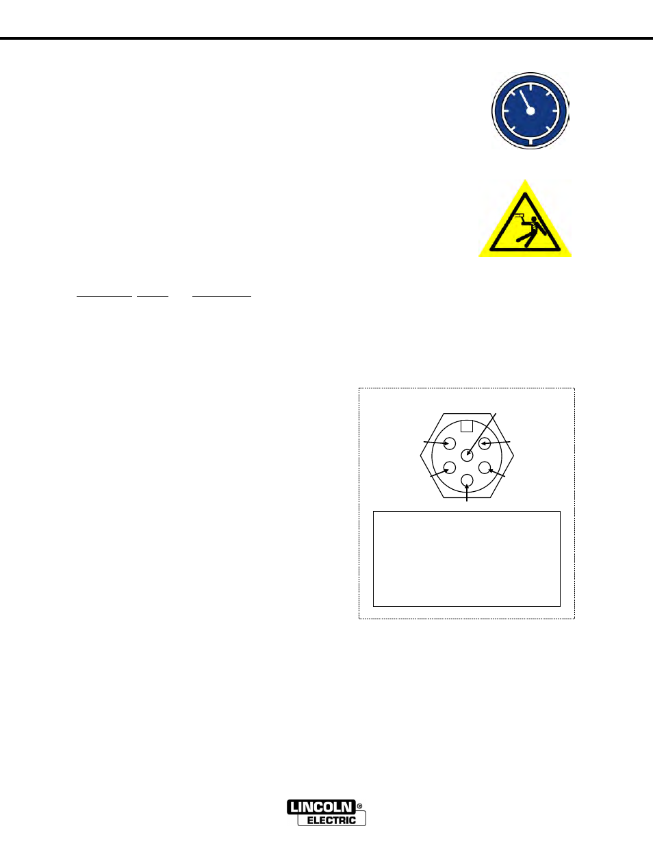
-Secure the 6-pin connector into the receptacle on the base of the POWER
REAM and feed the other end through a strain relief into the robot
controller cabinet or other connection points on the robotic cell.
-Connect robot I/O signals according to the following description.
Electrical Diagram
Wire Color Name Description
Red
+24Vdc Power supply (+24Vdc, 0.5 amp)
White
0Vdc
Power supply return.
It is recommended that power to the reamer be wired concurrent with robot servo power,
interrupt-able by an E-stop condition.
Orange
Start
Robot output. Pulse this
output from the robot for
0.5sec to start the ream cycle.
Black
Spray
Robot output. Pulse this
output from the robot for
approx. 0.5 sec while
positioned over the sprayer.
To activate the
Wire Cutter,
turn on both the start and
spray outputs at the same
time or subsequently.
Green
Complete Robot input. The robot should
check this input before and
after a reaming cycle.
Blue
Error
Robot input. The robot can
check this input after a
reaming cycle to ensure error
free operation. Refer to
Diagnostics section for error
codes.
The POWER REAM detects sinking or sourcing outputs from the robot and is capable of sinking
or sourcing signals to the robot. Before connecting ensure I/O configuration is compatible with
robot. POWER REAM factory setup is for robots with sinking outputs and active high inputs.
1
2
3
4
5
6
Wiring
1. 0V DC
(WHT)
2. +24V DC
(RED)
3. Complete (GRN)
4. Start
(ORG)
5. Spray
(BLK)
6. Error
(BLU)
Interface Receptacle