5 full duplex parameter entry/recall, 2 delay demand print, 3 battery option – Rice Lake Condec UMC600 User Manual
Page 68: 2 delay demand print 8.3 battery option, The response data, Indicating the invalid portion
Optional and Advanced Features
65
8.1.5
Full Duplex Parameter Entry/Recall
One of the capabilities of the UMC600, with the full duplex serial port 1 is the ability to enter or recall setpoints
from a computer or terminal. The following table illustrates full duplex setpoint parameter entry/recall.
Table 8-2. Full Duplex Setpoint Parameter Entry/Recall
The response data (
xxxxx
) is corrected for count-by round off and is six characters in length if there is no decimal
point and seven with the decimal point. Leading zeros are spare characters.
Invalid data requests or entries are responded to with an echo of the valid portion and an
I
indicating the invalid
portion.
8.2
Delay Demand Print
When file 7.17 is enabled, a demand print, from either the print key or the remote print (TB3-10), is delayed for up
to 25 seconds if the scale is in motion. If the scale comes out of motion before the 25-second timer times out, the
UMC600 will do a print of the data. If the scale remains in motion, the demand print is aborted.
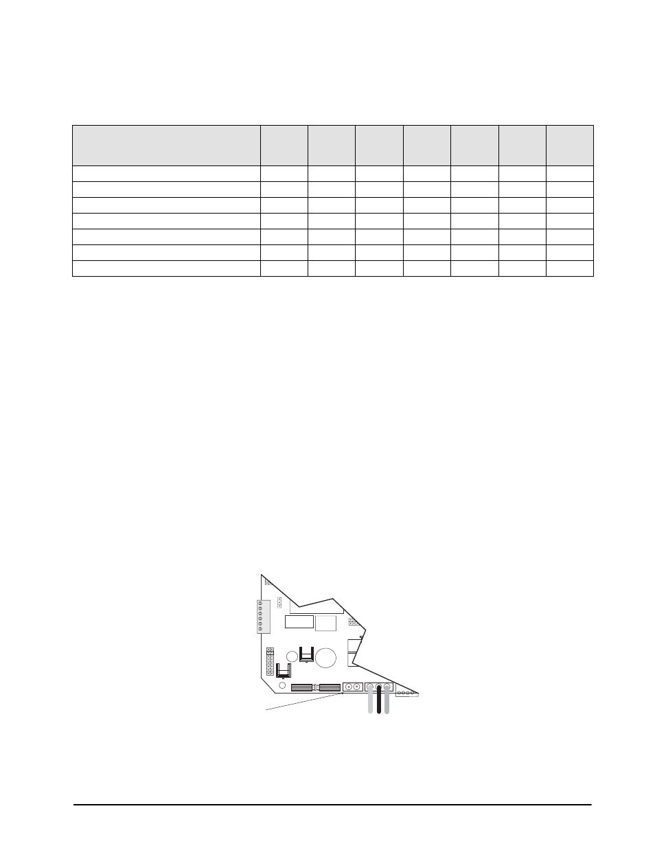
8.3
Battery Option
The UMC600 has an optional battery that can be installed. The indicator enclosure must be opened to connect the
battery to the CPU board. Use the following steps:
1. Disconnect AC power by unplugging the indicator.
2. Remove the screws that hold the front bezel to the enclosure body.
3. Place indicator face down on an antistatic work mat, then lift the back of the indicator away from the front
bezel.
4. Set the enclosure aside.
5. Locate the battery plug in on the CPU board (J6) shown in the diagram below. Plug in the connectors being
sure to note their polarity.
Figure 8-5. Battery Location
6. Mount the battery to the backplate and plug other end into battery located on the enclosure backplate. .
Setpoint Parameter
SE
SR
0
1
2
3
4
5
6
Mode A
all
SP1
SP2
Mode B
all
SP1
Pr1
SP2
Pr2
Mode C
all
SP1
dr1
SP2
dr2
Mode D
all
SP1
Pr1
dr1
SP2
Pr2
dr2
Mode E
all
SP1
Pr1
dr1
HI
Lo
Mode F
all
SP1
HIGH
Mode G
all
SP1
LOW
HIGH
J7
K1
S3
J5
J3
F1
J6
TB5
TB1
–EXC
–SEN
–SIG
+SIG
+SEN
+EXC
6
5
4
3
2
1
LOAD CELL CONNECTOR
1
2
U2
Q5
U18
GND LO HI
TO POWER SUPPLY
CPU Plug in
for Battery