1 serial port #1 wiring: cpu kgr8924–1, Tb4 tb2, Figure 2-13. serial port #1 switch location – Rice Lake Condec UMC600 User Manual
Page 13
10
UMC600 Installation Manual
2.11.1
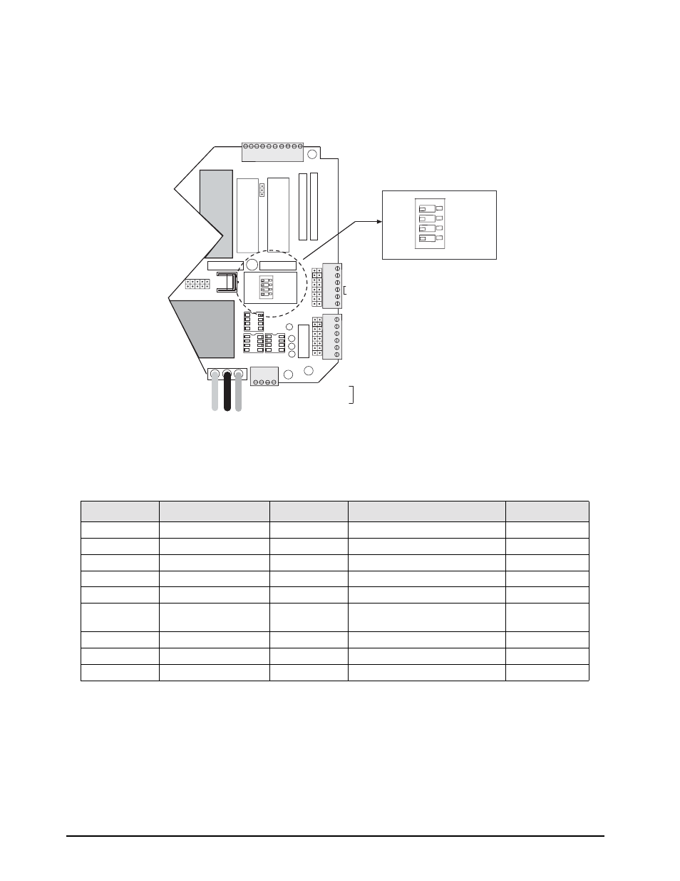
Serial Port #1 Wiring: CPU KGR8924–1
Serial Port 1 supports full-duplex RS-232, or 20mA current loop (active or passive), or half-duplex RS-485. Switch
S1 (shown below), selects the interface protocol of Port 1..
Figure 2-13. Serial Port #1 Switch Location
(
*
) Notes:
1. A pull-down biasing resistor (100K OHMS typical) should be installed between TB5-1 and TB2-5.
2. A pull-down biasing resistor (100K OHMS typical) should be installed between TB5-2 and TB2-4.
3. If the UMC600 is the last device (node) on the RS-485 network, a termination resistor (100 OHMS typical) should
be installed across TB5-1 and TB5-2.
Port
Connector/Pin #
RS-232
20mA Current Loop
RS-485
1
TB2 - 2
TxD
1
TB2 - 3
RxD
1
TB2 - 4
+20mA TX+ OUT (active)
*2
1
TB2 - 5
GND
-20mA RX- IN (active)
*1
1
TB2 - 6
-20mA TX- OUT (active)
1
TB4 - 3
+20mA RX+ IN (active)
-20mA RX- IN (passive)
1
TB4 - 4
+20mA RX+ IN (passive)
1
TB5 - 1
+20mA TX+ OUT (passive)
RS-485-A *1 *3
1
TB5 - 2
-20mA TX- OUT (passive)
RS-485-B *2 *3
Table 2-2. TB2, TB4, TB5 Pin Assignments (Serial Port #1 Communications)
U7
U4
U11
TB3
J2
TB5
6
5
4
3
2
1
SERIAL COMMUNICA
TIONS - 2
J11
J10
RX+ (20mA passive Port 1)
RX- (20mA passive Port 1)
RX+ (20mA active Port 1)
TX- (20mA Port 2)
TX+ (20mA Port 2)
TX- (20mA active Port 1)
GND or RX 20mA active Port 1
TX+ (20mA active Port 1)
RX1 (RS-232 duplex Port 1) RD1
TX1 (RS-232 duplex Port 1) TD1
TX2 (RS-232 Port 2) TD2
1
6
5
4
3
2
SERIAL COMMUNICA
TIONS - 1
1
6
5
4
3
2
1
7
8
9
10
DIGITAL OUTPUT
1
1
4
3
2
1
DIGITAL OUTPUT
U1
U10
U19
C15
U15
U22
U21
U8
U9
U13
TB4
TB2
GND LO HI
TO POWER SUPPLY
S1
3
4
1
2
RS232
20MA
RS485
ACTIVE
PORT 1 RECEIVE
PASS
S1
3
4
1
2
RS232
20MA
RS485
ACTIVE
PORT 1 RECEIVE
PASS
1 – +TD1 20mA passive/RS-485A
2 – -TD1 20mA passive/RS-485B
3 – +TD2 20mA passive
4 – -TD2 20mA passive
optional