9 standard surge protection board, Tb5 tb1, Caution – Rice Lake Condec UMC600 User Manual
Page 10: Check load cell color code for proper wiring, Six-pin female, Figure 2-9. surge protection diagram
Installation and Wiring
7
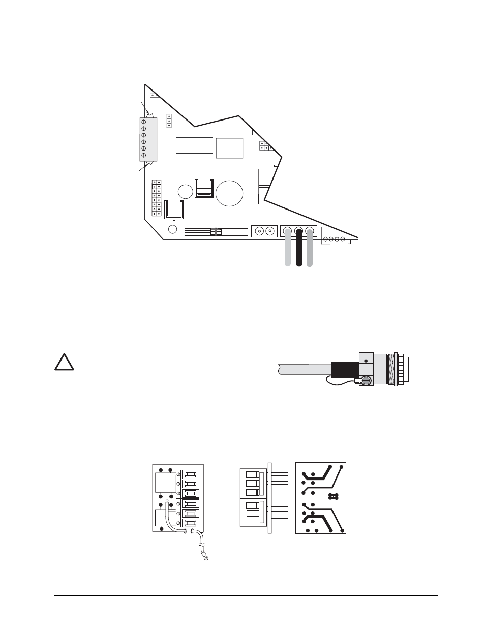
The standard connection is designed for 4-wire (non remote sensing) use. To convert to 6-wire (remote sensing)
applications, cut the two PC traces on each end of TB1 as shown in Figure 2-7.
Figure 2-7. Load Cell Wiring From Indicator
Note:
The load cell shield wire should be connected to
one of the load cell cable clamp screws located on the
load cell mating connector.
Shielding is connected at only one end
(typically at the indicator end). If
connected at the strain gauge end,
Figure 2-8. Load Cell Shield Wire Connection
2.9
Standard Surge Protection Board
The UMC600 comes with a factory installed surge suppression board. The suppression board stops the flow of
excess voltage to the CPU board and attaches to TB1 on the CPU board just by pressing it into TB1 and tightening
the connector screws.
Figure 2-9. Surge Protection Diagram
J7
K1
S3
J5
J3
F1
J6
TB5
TB1
–EXC
–SEN
–SIG
+SIG
+SEN
+EXC
6
5
4
3
2
1
LOAD CELL CONNECTOR
1
2
U2
Q5
U18
+ Batt -
GND LO HI
TO POWER SUPPLY
Check load cell
color code for
proper wiring.
Traces
Traces
!
Caution
Six-Pin Female
CR3
CR4
CR2
CR1
E1
E2
E3
E4
E5
E6
E7
CHGND
+EXC
+SENSE
+SIG
–SIG
–SENSE
–EXC
COMPONENT SIDE
RIGHT SIDE
CIRCUIT SIDE
- 1010 Potted & Unpotted Single Point, Aluminum (58 pages)
- 120 Digital Weight Indicator (44 pages)
- 120 Plus Digital Weight Indicator (56 pages)
- 320IS Intrinsically-Safe Digital Weight Indicator - Installation Manual (76 pages)
- 320IS Intrinsically-Safe Digital Weight Indicator - Timer Relay Instruction Sheet (2 pages)
- 320IS Intrinsically-Safe Digital Weight Indicator - Battery Charging Instruction Sheet (2 pages)
- 320IS Intrinsically-Safe Digital Weight Indicator - I/O Module for Intrinsically Safe Systems Installation Manual (15 pages)
- 320IS Intrinsically-Safe Digital Weight Indicator - IS-6V Battery Pack Instruction Sheet (6 pages)
- 320IS Intrinsically-Safe Digital Weight Indicator - IS-EPS-100-240 Power Supply Instructions (6 pages)
- 320IS Plus Intrinsically Safe Digital Weight Indicator - Installation Manual (90 pages)
- 420 Plus HMI Digital Weight Indicator Installation Manual (60 pages)
- 420 Plus HMI Digital Weight Indicator Operator Card (3 pages)
- 420 Plus Digital Weight Indicator - 7.5V DC-to-DC Power Supply Installation (4 pages)
- 420 Plus Digital Weight Indicator - IQ plus 355 - 390-DC - 590-DC & 420 Plus Quick Connector Cable Installation Instructions (1 page)
- 480 Legend Series Digital Weight Indicator Installation Manual (68 pages)
- 480 Legend Series Digital Weight Indicator Operator Card (1 page)
- 480 Panel Mount Option (4 pages)
- 520 Analog Output Card Installation (2 pages)
- 520 Digital Weight Indicator Operator Card (4 pages)
- 520 HMI Digital Weight Indicator Installation Manual (98 pages)
- 520 HMI Digital Weight Indicator Manual - BCD Option (18 pages)
- 520 Configurable Weight Indicator - Remote I/O Indicator Interface Installation and Programming Manual (31 pages)
- 520 Configurable Weight Indicator - ControlNet Interface Installation and Programming Manual (23 pages)
- 520 Configurable Weight Indicator - DeviceNet Interface Installation and Programming Manual (21 pages)
- 520 Configurable Weight Indicator - Ethernet Interface Installation and Configuration Manual (38 pages)
- 520 Configurable Weight Indicator - EtherNet/IP Interfac Installation and Programming Manual (26 pages)
- 520 Configurable Weight Indicator - Profibus DP Interface Installation and Programming Manual (21 pages)
- 550-10-1 Digital Chair Scale - Operation Manual (26 pages)
- 550-10-1 Digital Chair Scale - Technical Manual (34 pages)
- 590-AG Livestock Digital Weight Indicator (56 pages)
- 65059 Mild Steel 3-Module Kit - RL50210 Load Cell Mounting Kit Installation Guide (13 pages)
- 720i Programmable Indicator/Controller - 6V DC-to-DC Power Supply Installation Instructions (4 pages)
- 720i Programmable Indicator/Controller - Installation Manual (122 pages)
- 720i Programmable Indicator/Controller - Operator Card (4 pages)
- 720i Programmable Indicator/Controller - Analog Output Card Installation Instructions (4 pages)
- 720i Programmable Indicator/Controller - CW-90/90X - iQUBE2 - LaserLT WLAN Installation Instructions (12 pages)
- 720i Programmable Indicator/Controller - USB Interface Card Installation Instructions (2 pages)
- 820i Programmable Indicator/Controller - Installation Manual (112 pages)
- 820i Programmable Indicator/Controller - Panel Mount Enclosure Installation Instructions (6 pages)
- 880 Performance Series Indicator/Controller Operators Manual (36 pages)
- 880 Performance Series Indicator/Controller Technical/Service Manual (120 pages)
- 880 Performance Series Panel Mount Indicator/Controller - Adapter Panel Installation (4 pages)
- 880 Performance Series Panel Mount Indicator/Controller - Analog Output Card Option Installation Manual (6 pages)
- 880 Performance Series Panel Mount Indicator/Controller - DeviceNet Interface Option Installation and Programming Manual (28 pages)
- 880 Performance Series Panel Mount Indicator/Controller - EtherNet/IP Interface Option Installation and Programming Manual (32 pages)