Basic operation, Danger, Warning – Yokogawa In-Situ Gas Analyzer TDLS200 User Manual
Page 92: Caution
6-35
6-36
IM 11Y01B01-01E-A 6th Edition :Feb 13, 2013-00
<6. BASIC OPERATION>
If the analyzer connection cannot be established (see error message below) then check the PC IP settings,
connection wires/Cat5 cable and IP address.
TDLS200 TDL Analyzer Instruction Manual V2.1
Page 81 of 131
- 81 -
4.8.2 Using Ultra-VNC Software
Start the Ultra-VNC software by double-clicking on the “vncviewer.exe” ICON (as shown below):
Within the VNC Server field, enter the correct IP address for the analyzer to which you are
connecting then click on “Connect” button. If a successful connection is established then use the
default password for entering the VNC connection screen is 1234 – see screen below that shows
an example IP address of 10.0.2.14 (for an analyzer Serial number XX-1214-XX etc.):
DO NOT attempt to change of the “Quick Options” or any other settings on this menu!
If the analyzer connection cannot be established (see error message below) then check the PC IP
settings, connection wires/Cat5 cable and IP address.
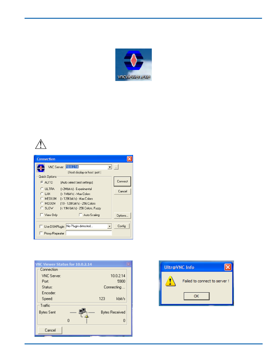
6.9.2 Using Ultra-VNC Software
Start the Ultra-VNC software by double-clicking on the “vncviewer.exe” ICON (as shown below):
Within the VNC Server field, enter the correct IP address for the analyzer to which you are connecting then click
on “Connect” button. If a successful connection is established then use the default password for entering the
VNC connection screen is 1234 – see screen below that shows an example IP address of 10.0.2.14 (for an ana-
lyzer Serial number XX-1214-XX etc.):
For analyzers with Serial/Tracking number XX.2xxx-xx, use IP address 10.0.20xx, for example 76H-2018-12-Ex
would have an IP address 10.0.20.18
For analyzers with Serial/Tracking number XX.3xxx-xx, use IP address 10.0.30xx, for example 23-3007-13-Ex
would have an IP address 10.0.30.7
DO NOT attempt to change of the “Quick Options” or any other settings on this menu!
2
All Rights Reserved. Copyright © 2011, Yokogawa Electric Corporation. Subject to change without notice.
January 2011
IM 11A00V01-01E-A
Operating and Maintenance Manual
1. Introduction ...................................................................................................4
1.1 Features ................................................................................................ 4
2. General Specifications .................................................................................5
3. Theory of Operation......................................................................................6
3.1 Brief History of Reflux Samplers ......................................................6
3.2 Filter Section .....................................................................................6
3.3 Steam Supplement ...........................................................................6
3.3 Inlet Temperature Section ................................................................6
3.4 Heat Exchanger Section ...............................................................6-7
3.5 Outlet Temperature Section .............................................................7
3.6 Self Acting Temperature Controller ..................................................7
3.7 Instrument Air for the Vortex Tube ...................................................7
3.8 Vortex Theory of Operation ..............................................................7
4. Utility Requirements .....................................................................................8
4.1 Instrument Air ...................................................................................8
4.2 Low Pressure Steam ........................................................................8
5. Installation .....................................................................................................9
5.1 Mechanical Considerations ..............................................................9
5.2 Fast Loop Line Size and Response Times .....................................9
5.3 Insulation ..........................................................................................9
6. Start-Up .......................................................................................................10
7. Operation .................................................................................................... 11
7.1 Vortex Tubes ................................................................................... 11
7.2 Steam Injection ............................................................................... 11
7.3 Controller ........................................................................................ 11
8. Maintenance ...............................................................................................12
8.1 Filter Section and/or Heat Exchanger Cleaning .......................12-13
9. Trouble Shooting ........................................................................................14
9.1 Vortex Tubes ...................................................................................14
10. Sub-Component Documentation .............................................................15
10.1 Vortex Tube Installation and Maintenance .............................15-17
10.2 Installation and Maintenance for SA Control Valve ...............18-24
11.2.1 General Safety ................................................................19
11.2.2 Tech. Details ...................................................................19
11.2.3 Install and Commiss ..................................................20-22
11.2.4 Maintenance ..............................................................23-24
10.3 Supplement Safety Information ...................................................25
10.3.1 Intended Use ..................................................................25
The following safety symbols are used on
the product as well as in this manual.
DANGER
This symbol indicates that an operator
must follow the instructions laid out in
this manual in order to avoid the risks, for
the human body, of injury, electric shock
or fatalities. The manual describes what
special care the operator must take to
avoid such risks.
WARNING
This symbol indicates that an operator must
refer to the instructions in this manual in
order to prevent the instrument (hardware)
or software from being damaged, or a
system failure from occurring.
CAUTION
This symbol gives information essential
for understanding the operations and
functions.
Note!
This symbol indicates information that
complements the present topic.