Analyzer components – Yokogawa In-Situ Gas Analyzer TDLS200 User Manual
Page 21
4-2
IM 11Y01B01-01E-A 6th Edition :Feb 13, 2013-00
<4. ANALYZER COMPONENTS>
Main Electronics Housing
• Back Plane circuit board
• Single Board Computer (SBC)
• FPGA signal Processing board
• Analog I/O circuit board
• Field electrical terminals are located on Back Plane
(and optional Analog I/O board).
• Optional Mini Display (4x20 VFD) shown
Check Gas Flow Cell
Short cell (gas tight chamber)
allows Zero Gas or Span gas to
flow through the measuring path for
on-line validation)
Laser Housing and Laser Module
• Laser diode and collimating lens assembly
• Laser module designed to be field
replaceable and purged to prevent
ambient air ingress.
• Housed in a stainless steel body with
O-rings seals, attached to the main
electronics housing.
Laser Assembly
Main
Electronic
Housing
Check Gas
Flow Cell
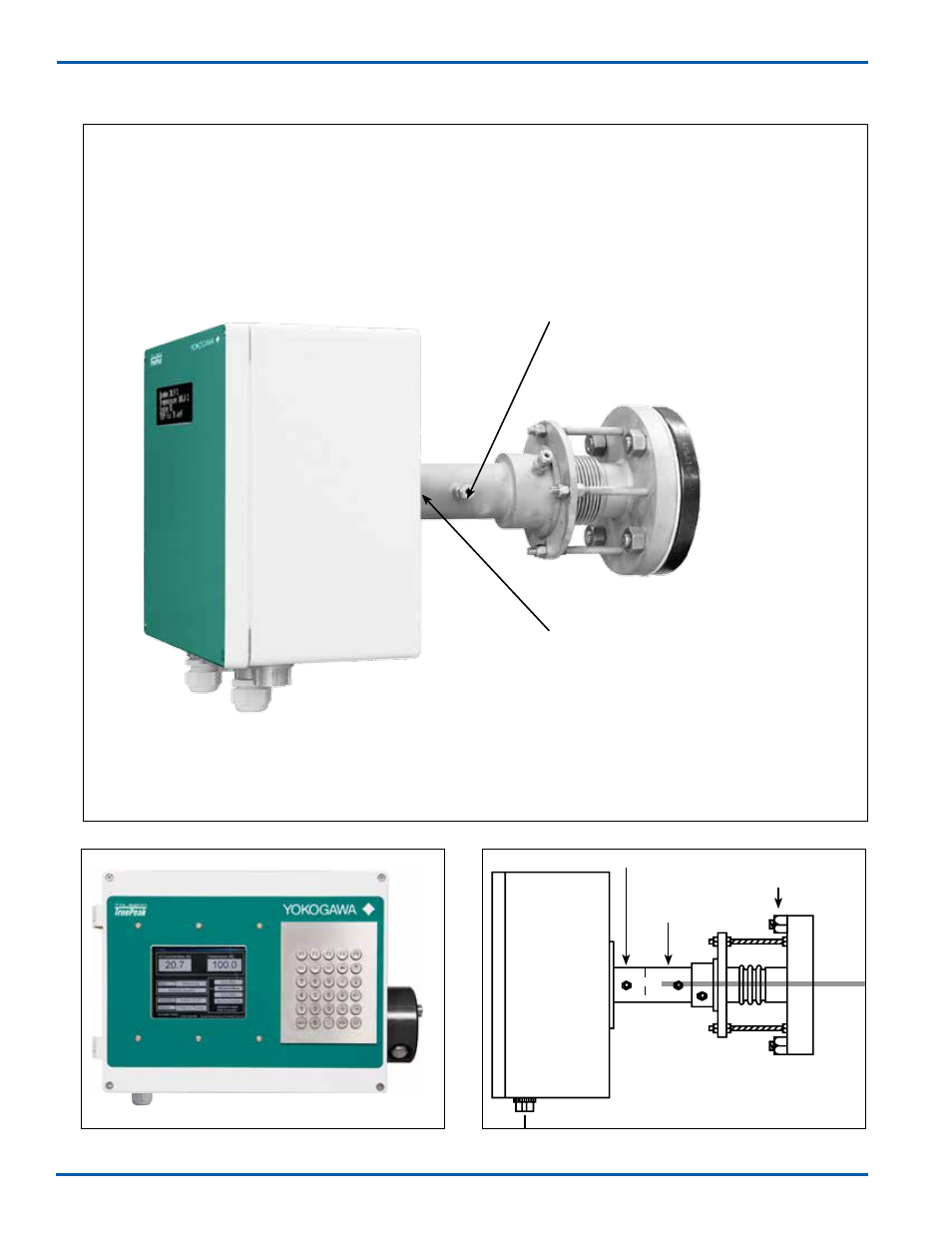
4.1 Launch Unit
Process
Interface
Figure 5 - Launch Unit - Optional Keypad and Display
Figure 7 - Launch Unit Overview
Figure 6 - Launch Unit-Optional Keypad & display