Introduction – Yokogawa digitalYEWFLO (DY) User Manual
Page 6
INTRODUCTION
IM 1F2B4-01-YIA
Page 2
The flapping flag is a familiar example of vortex shedding that everyone should be comfortable with.
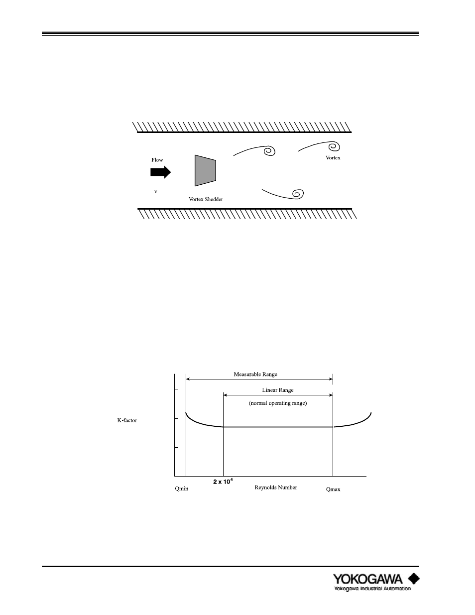
Here’s how it’s used in a vortex flowmeter. A non-streamlined part (bluff body) is inserted in the flow
stream, this obstruction in the pipe causes vortices to be alternately created (shed). We call this part
the ‘shedder bar’. The shedder bar in a YEWFLO performs two functions, it creates the vortices, and
with the addition of our piezoelectric crystals senses them too. The crystals generate an alternating
voltage waveform whose frequency is proportional to fluid velocity. The rest of the magic is taken care
of in the electronics.
Figure 1.2.1: Karman Vortices
1.2.2
K-factor
The most important fact about vortex shedding is that once the physical geometry, (pipe I.D., shedder
bar width, etc.), are fixed, the frequency vs. flowrate (K-factor (pulse/gallon)) is unaffected by
changes in viscosity, density or pressure over the operating range of the specific application. To
determine the operating range use the YEWFLO Sizing program. On the other hand, an orifice plate is
directly affected by changes in any of these parameters. There is a very small temperature effect due to
expansion or contraction of the shedder bar width, which is easily compensated. Therefore, the K-
factor created in our flow stand (all YEWFLOs are wet flow calibrated) on water, is accurate for gas
too! Not so with an orifice plate. The benefit here is simplified calculations, and fewer things that
can effect accuracy .
Figure 1.2.2: Relationship between K-factor and Reynolds Numbers