Installation – Yokogawa digitalYEWFLO (DY) User Manual
Page 40
IM 1F2B4-01-YIA
Page 44
INSTALLATION
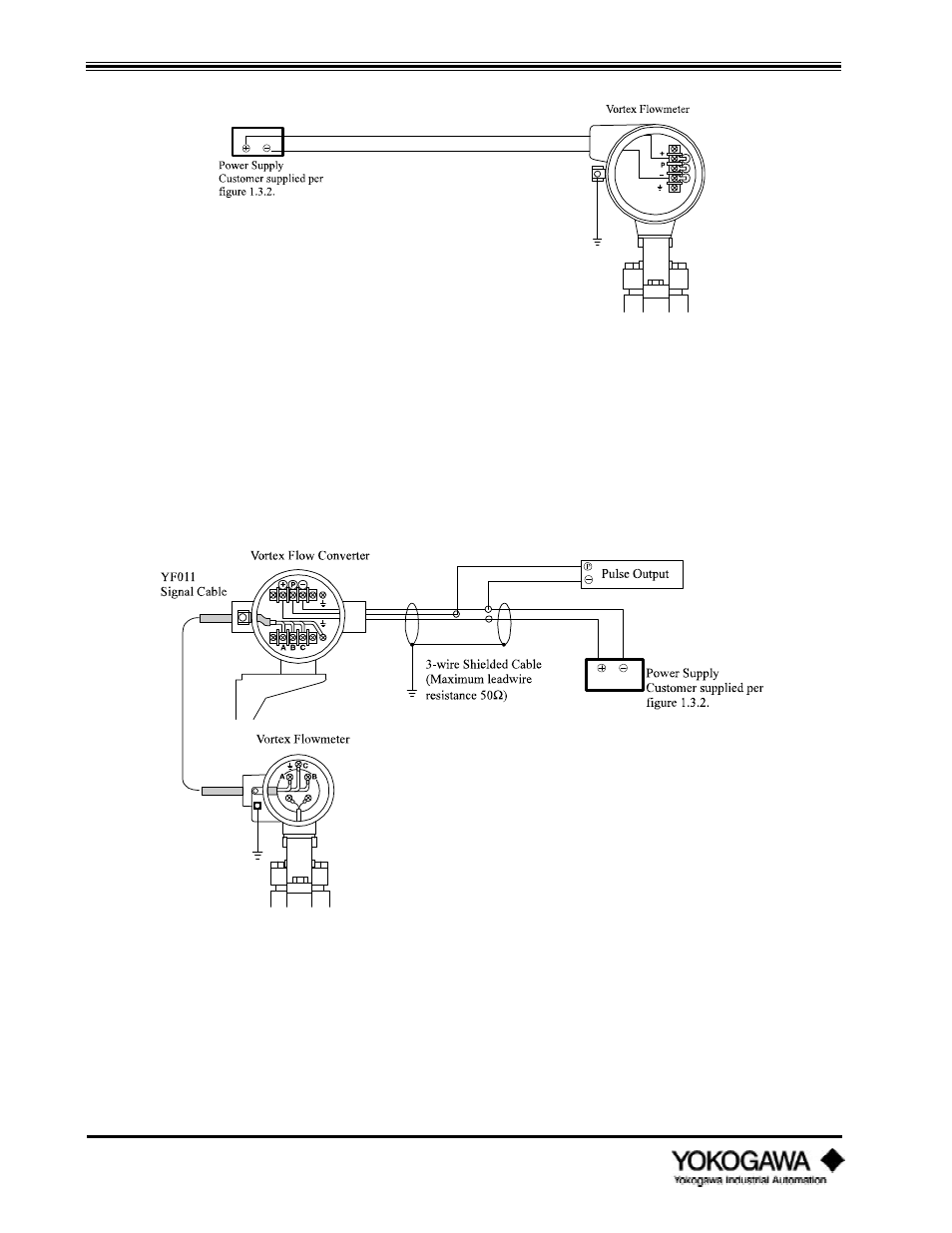
Figure 3.3.2: Wiring Connections (Analog) Integral Converter
3.3.3
Pulse output, 3-wire type
When configured for pulse output mode, the converter requires three wires between the converter
and the power supply. The required power should be between 18 and 30 VDC (allowable ripple +1.5
V or less). The pulse output (P terminal) is connected to a remote totalizer. The minimum load
resistance of the pulse output loop is 10k ohms (maximum capacitance 0.22F, 0.1F for output
frequency above 2.5 kHz), and interconnection wire resistance must be less than 50 ohms.
Figure 3.3.3: Wiring Connections (Pulse) - Remote Converter Type
See also other documents in the category Yokogawa Sensors:
- EJA115 (85 pages)
- EJA120A (47 pages)
- EJA120A (79 pages)
- EJA130A (2 pages)
- EJA130A (4 pages)
- EJA120A (31 pages)
- EJA130A (47 pages)
- EJA120A (40 pages)
- EJA438 (5 pages)
- EJA120A (6 pages)
- EJA210A (70 pages)
- EJA130A (4 pages)
- EJA430A (78 pages)
- EJA210E (52 pages)
- EJA210E (89 pages)
- EJA210E (170 pages)
- EJX120A (4 pages)
- EJA210E (9 pages)
- EJX115A (55 pages)
- EJA210E (41 pages)
- EJA210E (96 pages)
- EJX910A (83 pages)
- EJX910A (9 pages)
- EJX910A (103 pages)
- FlowNavigator Software (163 pages)
- EJX910A (55 pages)
- EJX910A (175 pages)
- EJA530A (67 pages)
- EJA120A (83 pages)
- EJX530A (52 pages)
- EJA110E (4 pages)
- EJA110E (85 pages)
- EJX120A (85 pages)
- EJA118 (76 pages)
- EJX118A (64 pages)
- EJA438 (72 pages)
- EJA430E (85 pages)
- EJX430A (40 pages)
- EJX430A (76 pages)
- EJA430E (7 pages)
- EJX430A (6 pages)
- EJA430E (41 pages)
- EJA430E (96 pages)
- EJX438A (10 pages)
- ADMAG AXR (194 pages)