Appendix a: parameter details – Yokogawa digitalYEWFLO (DY) User Manual
Page 113
Appendix A: Parameter Details
IM 1F2B4-01-YIA
Page 108
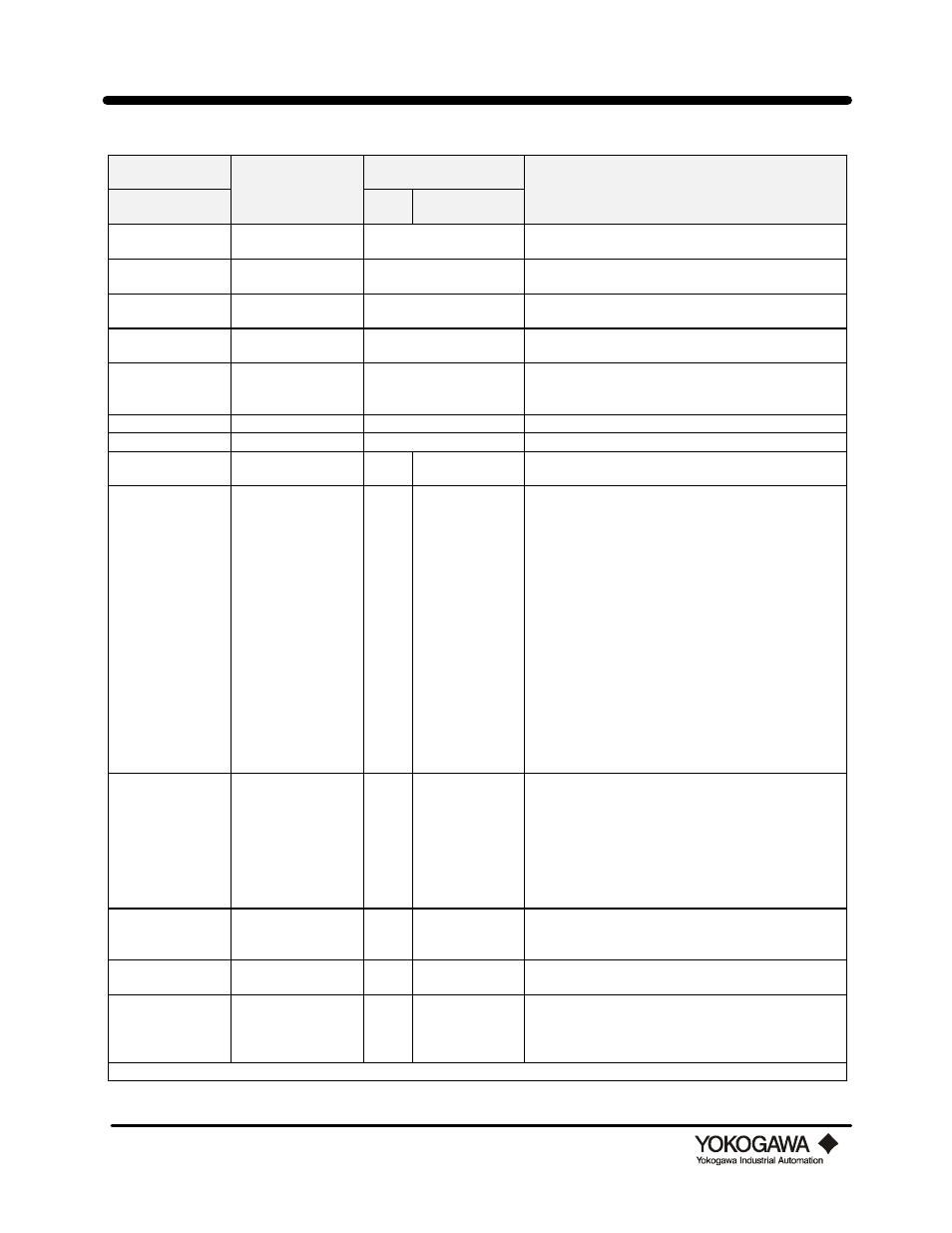
Hand Held
Terminal
Data Range
Indicator/Interface
Help / Remarks
Parameter No. and
Name
Prmtr
No.
Code No.
A: Display
Read only
No access
Beginning of Menu A which provides real time
information. on flow.
A10: Flow Rate%
0.0 to 110.0
Read only
No access
Flow rate in % of span is displayed and updated every
5 sec.
A20: Flow Rate
0 to 65535
Read only
No access
Actual flow rate is displayed in desired engineering
units and updated every 5 sec.
A30: Total
0 to 999999
Read only
No access
Totalized flow is displayed along with the total units
and updated every 5 sec.
A60: Self-check
Good
Error
Read only
No access
Diagnostic self-check. If good is displayed no error
exists. See “How To Use Diagnostics” for details.
B: Set 1
Read only
No access
Beginning of Menu B for basic configuration settings.
B01: Tag No.
16 characters
No access
Customer designated alphanumeric tag no.
B02: Output
4 to 20 mA
Pulse
02
0
1
Select the output mode. See “How to change the output
mode to Analog or Pulse” for details.
B03: Size
.5 in (15 mm)
1 in (25 mm)
1.5 in (40 mm)
2 in (50 mm)
3 in (80 mm)
4 in (100 mm)
6 in (150 mm)
8 in (200 mm)
2 in (50 mm HPT)
3 in (80 mm HPT)
4 in (100 mm HPT)
6 in (150 mm HPT)
8 in (200 mm HPT)
1 in (25 mm HPT)
1.5 in (40 mm HPT)
10 in (250 mm)
12 in (300 mm)
03
0
1
2
3
4
5
6
7
8
9
10
11
12
13
14
15
16
Select the meter size from this list.
NOTE: The HPT code signifies that the sensor is
designed for High Process Temperature. Use the HPT
settings only if the /HPT option code is shown on the
flow meter nameplate. The HPT operating range is
575º - 750°F.
The meter size is displayed in mm only.
B04: Fluid
Steam M
Steam H
Steam Qf
Gas Qn
Gas M
Gas Qf
Liq Qf
Liq M
04
0
1
2
3
4
5
6
7
Select the fluid type to be measured:
M refers to mass flow units (i.e. lb/hr)
H refers to energy flow (i.e. Btu/hr)
Q refers to volumetric flow
n refers to standard conditions (i.e. SCFM)
f refers to operating conditions (i.e. ACFH or GPM)
B05: K-Factor Units P / l
P / US gal
P / UK gal
05
0
1
2
Select the units for the K factor which will be entered
below in B06.
B06: K - Factor
0.00001 to 32000
06
0.00001 to 32000 Enter the K-factor (at 59°F) as stamped on the flow
meter body.
B07: Density Units
kg/m3
lb/acf
lb/US gal
lb/UK gal
07
0
1
2
3
Select the fluid density units.