Installation – Yokogawa digitalYEWFLO (DY) User Manual
Page 43
INSTALLATION
IM 1F2B4-01-YIA
Page 47
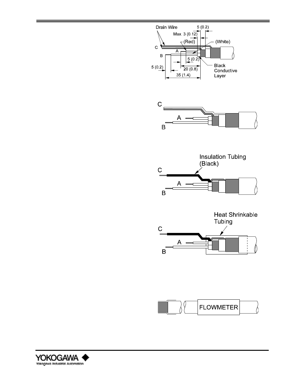
dimensions shown. Cut the length
of each wire to the dimensions
shown. Twist the strands of each
wire and drain wire so there are no
free strands.
3.
Do not allow the black conductive
layer to short circuit to wires A, B,
C or the metal Case.
4.
Strip off the red or white insulation
to the dimensions indicated. Twist
the outer and the inner drain wires
(shields) together. You should now
have 3 individual conductors.
5.
Insert insulating tubing over the
twisted drain wires, wire C, as far
as possible. Cut the tubing off
leaving only 0.2 inches (5 mm) of
the drain wire exposed. Strip 0.2
inches (5 mm) of insulation from
the tips of the remaining two wires,
A and B.
6.
Slide heat shrinkable tubing over
the wire bundle such that it covers
the braided shields, overlaps the
outer jacket and the loose wires A,
B, and C as shown. Be certain that
this tubing insulates all shield wires
from chassis ground, this will insure
that the field ground remains
isolated from the control room
ground.
7.
Install insulated crimp lugs on each
wire A, B, and C.
8.
Attach identifying labels to the
outside of the signal cable.