Installation – Yokogawa digitalYEWFLO (DY) User Manual
Page 34
IM 1F2B4-01-YIA
Page 38
INSTALLATION
3.1.4
Flushing the pipe
On a new installation we recommend flushing the pipeline and removing any and all scales on the
inside of the pipe before installing the vortex meter. The bypass piping should be installed around the
vortex meter to facilitate pipe cleaning. When there is no bypass piping, the vortex meter should be
temporarily removed and a spool piece installed in its place.
3.1.5
Gaskets
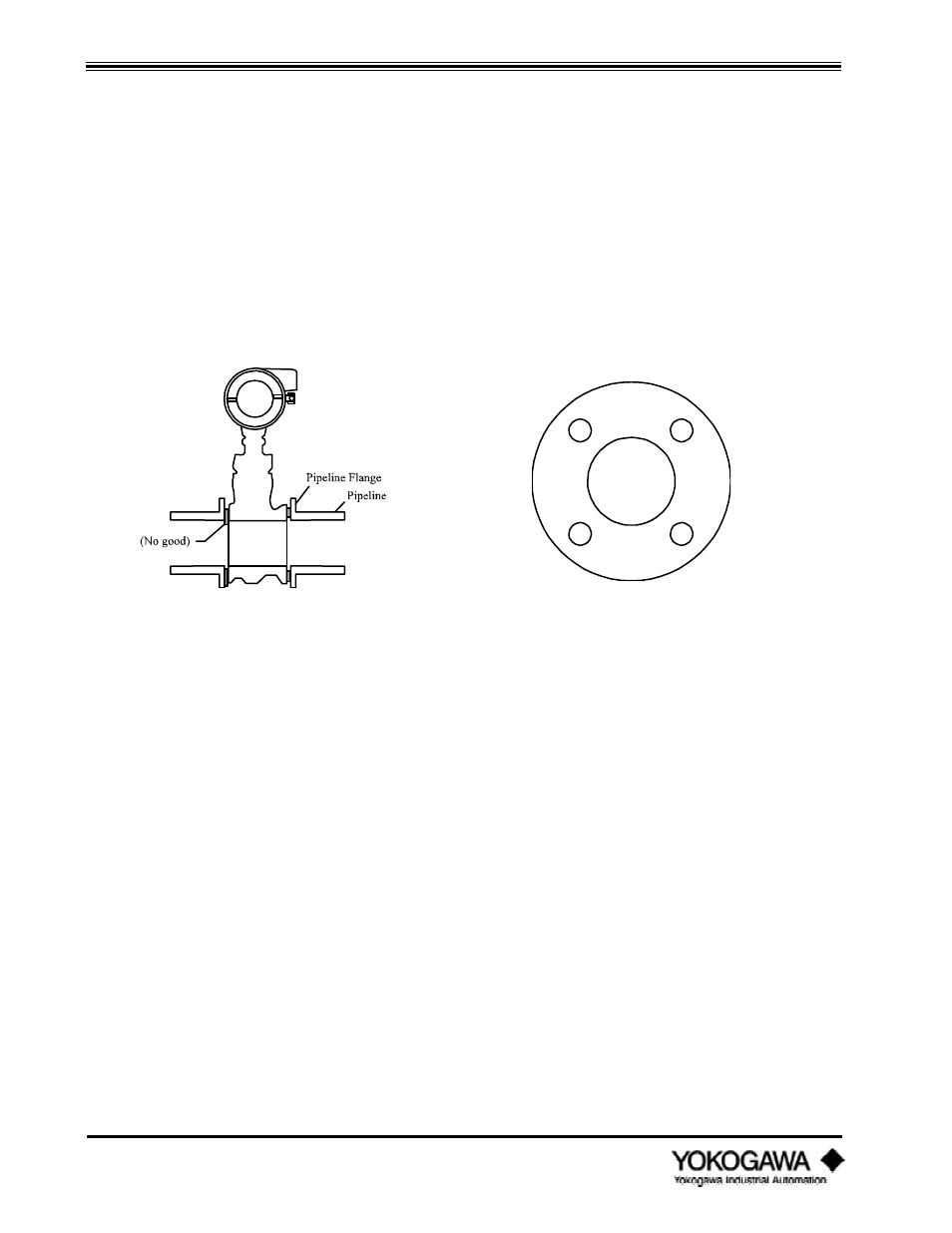
The ID of the gaskets must be equal to or larger than the ID of the meter and mating pipe. The
gaskets should be the self-centering type. It is important that the gaskets not protrude into the flow
stream, otherwise accuracy will be adversely affected.
Figure 3.1.4: Gasket cross section
Figure 3.1.5: Typical gasket with bolt holes
3.2
I
NSTALLING
THE
V
ORTEX
M
ETER
Before installing the vortex meter, verify the arrow on the meter body is facing the same direction as
the direction of the flow.
3.2.1
Installing the wafer style vortex meter
When installing the wafer type vortex meter it is important to align the instrument bore with the
inner diameter of the adjacent piping. For meters in sizes ½" through 3", four alignment collars are
supplied. These collars establish a predetermined spacing between the mounting bolts and the
outside diameter of the vortex meter body. The bolts must be of the proper diameter to establish
alignment. Carbon steel stud bolts and nuts are supplied as standard. Stainless steel (304) stud bolts
and nuts are optional. Gaskets are supplied by the user. Check all mating flanges ensuring all weld
slag is ground off and the inside surface is clean and smooth.