Installation – Yokogawa digitalYEWFLO (DY) User Manual
Page 35
INSTALLATION
IM 1F2B4-01-YIA
Page 39
Meter
Flange
Collar Kit
Mark on
Size
Rating
(4 per set)
collar
0.5"
150#
F9322GC
GL
0.5"
300#, 600#
F9322GD
GM
1.0"
150#
F9322HC
HL
1.0"
300#, 600# F9322GA
GJ
1.5"
150#
F9322GC
GL
1.5"
300#, 600#
F9322JD
JM
2.0"
150#
F9322KA
KC
3.0"
150#
F9322KM
KP
Table 3.2.1: Dimensions
Note:
Only the above indicated meter sizes require collars
3.2.2
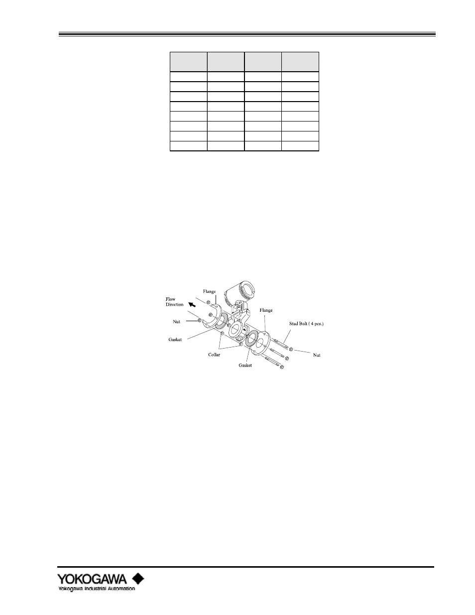
Installing the wafer style vortex meter horizontally
1)
Insert two collars (see dimensions table above) on each of the two lower bolts.
2)
Place the vortex meter on the collars located on the lower two bolts making sure the arrow
on the side of the meter body is facing in the same direction as the flow.
3)
Insert the remaining bolts and tighten all bolts and nuts uniformly.
4)
Check for leakage between the meter body and the flanges.
Figure 3.2.1: Wafer type - horizontal installation
3.2.3
Installing the wafer style vortex meter vertically
1)
Insert one collar (if required, see table 3.2.1) on each bolt, being certain that the collars are
in contact with the outside diameter of the vortex meter body. Make sure the arrow on the
side of the meter body is facing the same direction as the flow.
2)
Tighten all bolts uniformly.
3)
Check for leakage between the meter body and the flanges.