Installation – Yokogawa digitalYEWFLO (DY) User Manual
Page 41
INSTALLATION
IM 1F2B4-01-YIA
Page 45
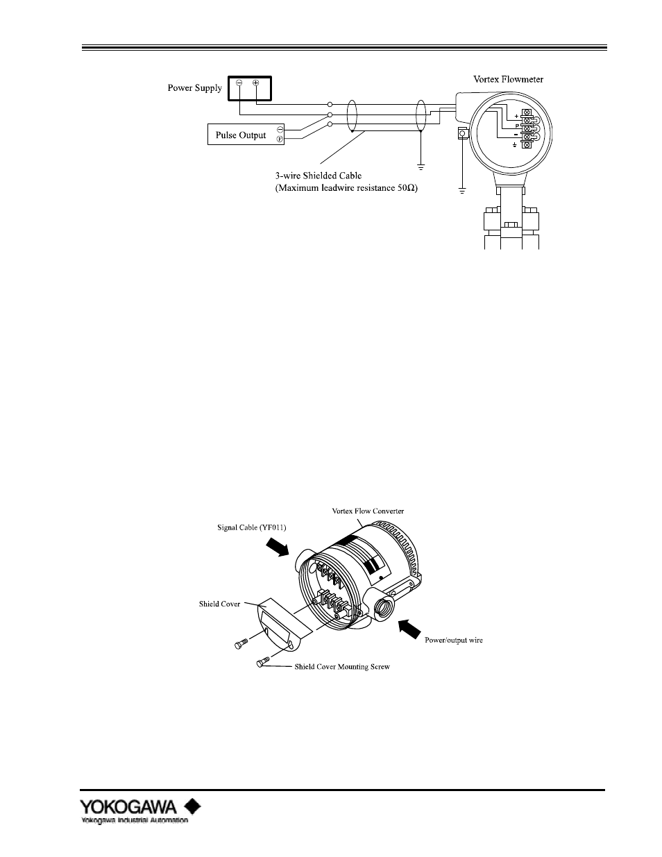
Figure 3.3.4: Wiring Connections (Pulse) - Integral Type
3.3.4
Interconnection for remote converter
When the converter is remotely mounted from the meter body, a special signal cable (YFO11) must
be used. The maximum length of this cable is 65 feet (20 meters). The signal cable transmits a low
level sensor signal from the remote flowmeter to the remote converter. The remote converter
provides the output signals as described above. The remote signal wire connections are the same for
either Analog or Pulse output units. The A, B and C terminals on the flowmeter are connected via the
red, white and black wires (respectively) to the A, B and C terminals on the converter. The blue wire
is connected on the converter end only to chassis ground. See figure 3.3.5.
For remote mounted converters there are two electrical conduit connections. Use the left connection,
as viewed from the terminal side, for the signal wire (YFO11 cable) and the right connection for the
output wiring. If the connection directions are reversed, the cover shield for the signal terminals
cannot be installed.
Figure 3.3.5: Shield Converter -Remote Type