Appendix a: parameter details – Yokogawa digitalYEWFLO (DY) User Manual
Page 118
Appendix A: Parameter Details
IM 1F2B4-01-YIA
Page 113
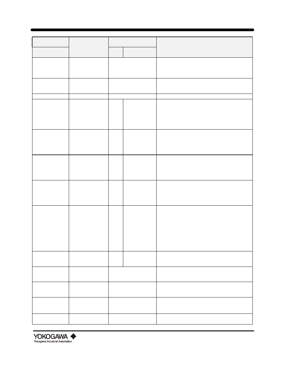
Hand Held
Terminal
Data Range
Indicator/Interface
Help / Remarks
Parameter No. and
Name
Prmtr
No.
Code No.
G22: Min Flow
Read only
No access
Minimum flow reading since the last execute of G20.
Display value 0 - 110% span.
G60: Self-check
Good
Error
Read only
No access
Diagnostic self-check. If good is displayed no error
exists. See “How To Use Diagnostics” for details.
H: Maintenance
Read only
No access
This signifies the beginning of the Maintenance Menu.
H01: N. Balance
-5 to 10
Factory Set
H1
-5 to 10
Noise Balance:
This parameter is factory set to match the sensor
crystals for maximum signal to noise ratio. Field
adjustment should be done only by a trained
technician, or as directed by the Factory. Refer to
“Troubleshooting” for more details.
H02: TLA
-1
0
1
2
default is 0
H2
Trigger Level Adjustment: Factory default is 0
This adjustment is used to suppress the effects of pipe
vibration noise on the output signal. -1 is very sensitive
and 2. Refer to “Troubleshooting” for more details
H03: Gain
16 steps
default is 0
H3
16 steps
Amplifier Gain: Factory default is 0
Gain is set automatically by values input in the B
menu. Consult the factory prior to adjusting this
parameter, or refer to “Troubleshooting” for more
details.
H04: H. F. Filter
16 steps
default is 0
H4
16 steps
High Frequency Filter: Factory default is 0
Filter is set automatically by values input in the B
menu. This parameter is used to high frequency noise.
Consult the factory prior to adjusting this parameter, or
refer to “Troubleshooting” for more details.
H06: Noise Judge
Not active
Active
H6
0
1
Dynamic Noise Reduction:
This parameter determines if the input received is
noise or flow signal by comparing amplitude and
frequency to predicted values. Parameter B08 Min.
Density Flowing adjusts the cutoff value of this
function up and down. When injecting a frequency
signal into TP2 for amplifier calibration this parameter
must be in the Not Active mode. Refer to
“Calibration” and “Troubleshooting” for details.
H07: L.C. Flowrate
0.00001 to B52 value
H7
0.00001 to B52
This parameter sets the low flow cut off value. Any
signal below this value will be ignored. Refer to “How
to set the Low Flow cutoff value” for details.
H08: Trim 4 mA
-1.0000 to 10.000 %
No access
This parameter is used for fine adjustment of the 4 mA
output. Refer to “How to trim the 4-20 mA output” for
more details.
H09: Trim 20 MA
-10.000 to 10.000 %
No access
This parameter is used for fine adjustment of the 20
mA output. Refer to “How to trim the 4-20 mA output”
for more details.
H10: CLR. Err2
Not active
Active
No access
ERR #2 on the local indicator, warns that the span value
in B52 exceeds 32.8 ft/sec for liquids, or 262 ft/sec for
gas or steam. Select Active to disable this warning.
H20: Measure TP2
Not execute
Execute
No access
Select Execute to allow digital display of the TP2 test
point voltage in parameter H21 (Volts, peak-to-peak).