Yokogawa ADMAG AXF User Manual
Page 85
IM 01E20D01-01E
6-23
6. OUTLINE
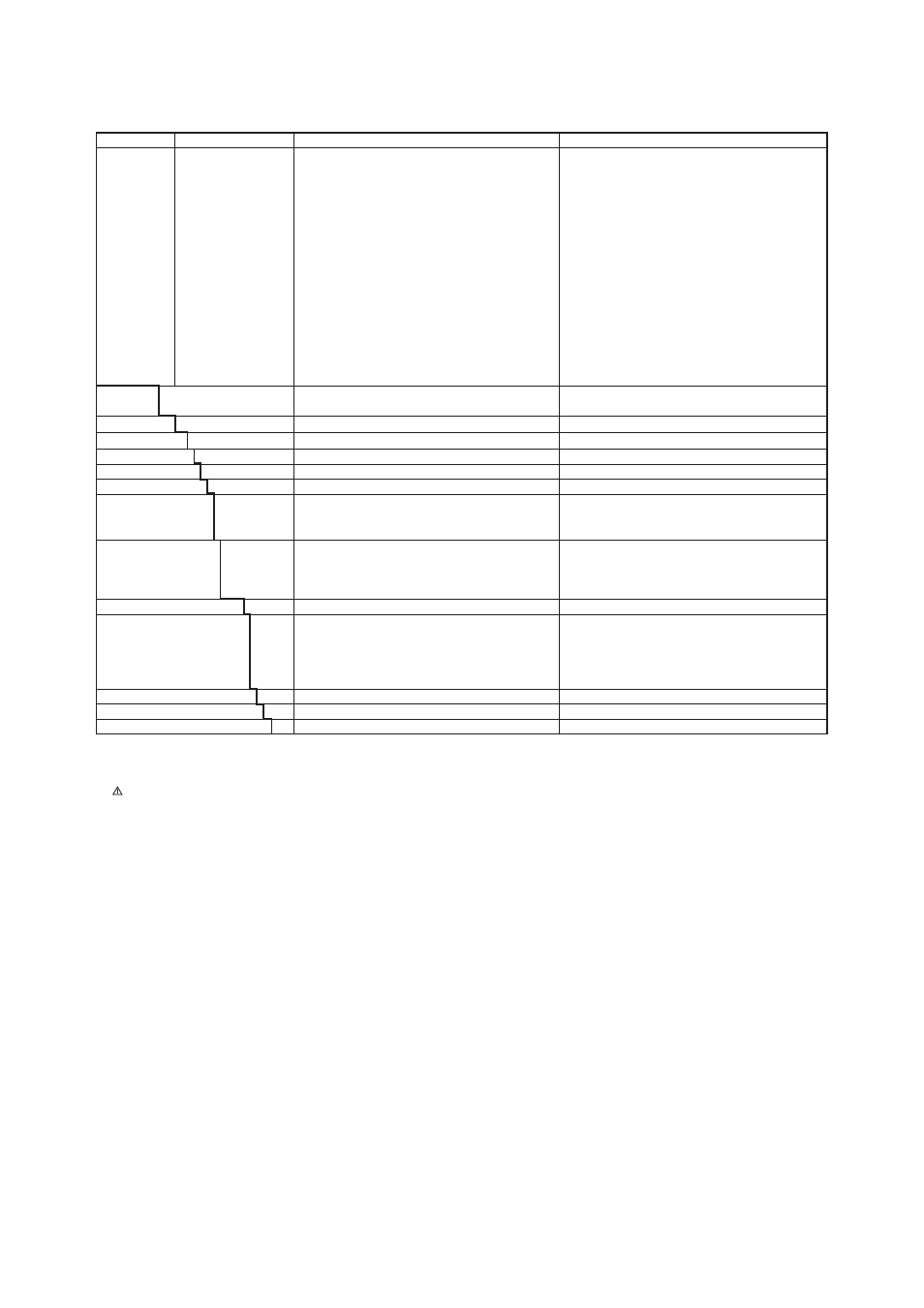
AXF STANDARD (Flange Type) Size 500 mm (20 in.) to 2600 mm (104 in.)
General-purpose Use/Submersible Type, Polyurethane Rubber Lining
Use
Converter
Power Supply
Lining (*4)
Electrode Material (*4)
General-Purpose Use
Submersible Type
Remote Flowtube for Combined Use with AXFA11
Remote Flowtube
JIS SUS316L(AISI 316L SS/EN 1.4404 Equivalent)
Non-replaceable
JIS SUS304 (AISI 304 SS/EN 1.4301 Equivalent)
SS400 Carbon Steel lined with Stainless Steel SUS316
(AISI 316 SS/EN 1.4401 Equivalent)
-N · · · · · · · · · · · · · · · · · ·
G · · · · · · · · · · · · · · · · · · · · ·
W · · · · · · · · · · · · · · · · · · · · ·
Polyurethane Rubber
Grounding Ring material
(*4)
Process Connection
(*1)(*5)
ANSI Class 150 Flange (Carbon Steel) (*2)
DIN PN10 Flange (Carbon Steel) (*2)
JIS 10K Flange (Carbon Steel) (*2)
JIS F12 (JIS 75M) Flange (Carbon Steel) (*2)(*3)
Size 500 mm (20 in.), 600 mm (24 in.)
Size 500 mm (20 in.) to 1000 mm (40 in.)
Size 500 mm (20 in.) to 1000 mm (40 in.)
Size 500 mm (20 in.) to 2600 mm (104 in.)
Size 500 mm (20 in.) to 1000 mm (40 in.), Not available for
Submersible Type
Size 500 mm (20 in.) to 1000 mm (40 in.), Not available for
Submersible Type
Size 500 mm (20 in.) to 1000 mm (40 in.)
Size 1100 mm (44 in.) to 2600 mm (104 in.)
Lay Length
1 · · · · · · ·
Standard
Optional code (See the Table of Optional Specifications)
Electrical Connection
AXF Standard
B · · ·
Calibration
Options
None
Indicator
-0 · · · ·
-2 · · · ·
-4 · · · ·
JIS G1/2 female
ANSI 1/2 NPT female
ISO M20
ϫ1.5 female
N · · ·
/
ٗ
Electrode Structure
-CA1
· · · · · ·
-CD1 · · · · · ·
-CJ1
· · · · · ·
-CG1 · · · · · ·
S · · · · · · · · · · · ·
1· · · · · · · · · · · · · ·
L
· · · · · · · · · · · · ·
N · · · · · · · · · · · · · · · ·
U
· · · · · · · · · · · · · ·
Model
Suffix Code
Description
Applicable Model
AXF500
AXF600
AXF700
AXF800
AXF900
AXF10L
AXF11L
AXF12L
AXF13L
AXF15L
AXF16L
AXF18L
AXF20L
AXF22L
AXF24L
AXF26L
· · · · · · · · · · · · · · · · · · · ·
· · · · · · · · · · · · · · · · · · · ·
· · · · · · · · · · · · · · · · · · · ·
· · · · · · · · · · · · · · · · · · · ·
· · · · · · · · · · · · · · · · · · · ·
· · · · · · · · · · · · · · · · · · · ·
· · · · · · · · · · · · · · · · · · · ·
· · · · · · · · · · · · · · · · · · · ·
· · · · · · · · · · · · · · · · · · · ·
· · · · · · · · · · · · · · · · · · · ·
· · · · · · · · · · · · · · · · · · · ·
· · · · · · · · · · · · · · · · · · · ·
· · · · · · · · · · · · · · · · · · · ·
· · · · · · · · · · · · · · · · · · · ·
· · · · · · · · · · · · · · · · · · · ·
· · · · · · · · · · · · · · · · · · · ·
Size 500 mm (20 in.) Remote Flowtube
Size 600 mm (24 in.) Remote Flowtube
Size 700 mm (28 in.) Remote Flowtube
Size 800 mm (32 in.) Remote Flowtube
Size 900 mm (36 in.) Remote Flowtube
Size 1000 mm (40 in.) Remote Flowtube
Size 1100 mm (44 in.) Remote Flowtube
Size 1200 mm (48 in.) Remote Flowtube
Size 1350 mm (54 in.) Remote Flowtube
Size 1500 mm (60 in.) Remote Flowtube
Size 1600 mm (64 in.) Remote Flowtube
Size 1800 mm (72 in.) Remote Flowtube
Size 2000 mm (80 in.) Remote Flowtube
Size 2200 mm (88 in.) Remote Flowtube
Size 2400 mm (96 in.) Remote Flowtube
Size 2600 mm (104 in.) Remote Flowtube
T18-1.EPS
*1: Mating dimensions are based on standards as follows:
ANSI:ASME B 16.5, DIN: DIN 2501, JIS:JIS B 2220 and JIS G 3443-2
*2: Carbon steel Flange Material: JIS SS400(EN S275 Equivalent) or SFVC 2A
*3: There are no differences in dimensions of mating faces between JIS F12(JIS 75M) and JIS 7.5K.
*4:
Users must consider the characteristics of selected wetted parts material and influence of process fluids.
The use of inappropriate materials can result in the leakage of corrosive process fluids and cause injury to personnel and/or damage to plant facilities. It is
also possible that the instrument itself can be damaged and that fragments from the instrument can contaminate the user's process fluids.
Be very careful with highly corrosive process fluids such as hydrochloric acid, sulfuric acid, hydrogen sulfide, sodium hypochlorite, and high-temperature
steam (150
°C [302°F] or above). Contact Yokogawa for detailed information of the wetted parts material.
*5: Allowable fluid pressure should also be limited according to fluid temperature and pressure.