Yokogawa ADMAG AXF User Manual
Page 15
IM 01E20D01-01E
3-5
3. INSTALLATION
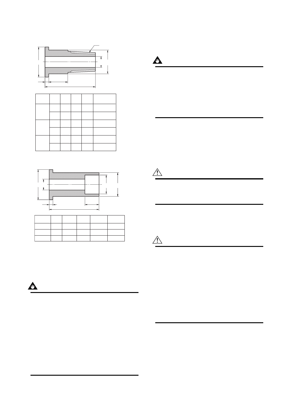
Table 3.3.1
Fitting Dimensions
Size
mm(inch)
Code
A
B
C
D
2.5
(0.1)
10
(0.4)
5
(0.2)
GUR
GUN
GUR
GUN
GUR
GUN
22
(0.87)
22
(0.87)
22
(0.87)
22
(0.87)
25
(0.98)
25
(0.98)
8
(0.31)
8
(0.31)
8
(0.31)
8
(0.31)
10
(0.39)
10
(0.39)
18.5
(0.73)
18.5
(0.73)
18.5
(0.73)
18.5
(0.73)
22.5
(0.89)
22.5
(0.89)
R1/4(PT1/4)
NPT1/4
R1/4(PT1/4)
NPT1/4
R3/8(PT3/8)
NPT3/8
D
A
4
(0.16)
11.5(0.45)
30(1.18)
B C
0
-0.1
Screw joint (process connection codes: GUR and GUN)
T0301.EPS
A B
4
(0.16)
35(1.38)
10(0.39)
+0.3
0
0
-0.1
C
D
Weld joint (process connection code: GUW)
Size
mm(inch) Code
GUW
GUW
GUW
A
B
C
D
T0302.EPS
2.5 (0.1)
10 (0.4)
5 (0.2)
22(0.87)
22(0.87)
25(0.98)
8(0.31)
8(0.31)
10(0.39)
14.3(0.56)
14.3(0.56)
17.8(0.70)
18.5(0.73)
18.5(0.73)
22.5(0.89)
(1) Mounting Direction
Mount the flowmeter so that the flow direction of the
fluid to be measured is in line with the direction of the
arrow mark on the flowmeter.
IMPORTANT
If it is impossible to match the direction of the
arrow mark, the direction of the electrical con-
nection can be changed. Refer to Section 5.1 to
do this properly.
In case the fluid being measured flows against
the arrow direction, refer to the parameter J20:
Flow Direction in the user’s manual of the
AXFA11 Magnetic Flowmeter Remote Converter
(IM 01E20C01-01E) or the AXFA14 Magnetic
Flowmeter Remote Converter/AXF Integral
Flowmeter [Software Edition] (IM 01E20C02-
01E).
(2) Connecting Process Piping
Weld or screw the connection fittings to the process
piping.
IMPORTANT
• Be sure to pass the connection fittings through
the union joint nuts in advance.
• When welding the fittings, pay attention to the
edge preparation, level differences between the
fittings and the piping, and the welding current
to avoid deforming the piping or causing
stagnation portion of the fluid.
(3) Positioning the Flowmeter
Install the flowmeter on a mounting base and position
it so that the center axis of the flowtube is aligned with
that of the process piping. Then screw the union joint
nuts to the connecting ports of the flowmeter.
CAUTION
Ceramics pipes may be damaged if the nuts are
tightened when the center axes are not properly
aligned.
(4) Tightening Nuts
Use a torque wrench to tighten the union joint nuts.
CAUTION
Tighten the union joint nuts according to the
tightening torque values in Table 3.3.2. For
permeable fluid (such as nitric acid, hydrofluoric
acid or sodium hydrate at high temperature),
tighten the nuts according to the torque values in
Table 3.3.3.
As the gasket material is fluorocarbon PTFE, it is
possible that the nuts may loosen as time
passes. Retighten the nuts if this is the case. Be
sure to use the gasket (thickness is 1.5 mm)
which comes with the flowmeter.