2 setting of write protect switch, 6 regular inspectionitems, Setting of write protect switch -9 – Yokogawa ADMAG AXF User Manual
Page 58: Regular inspection items -9, 6 regular inspection items
IM 01E20D01-01E
5-9
5. MAINTENANCE
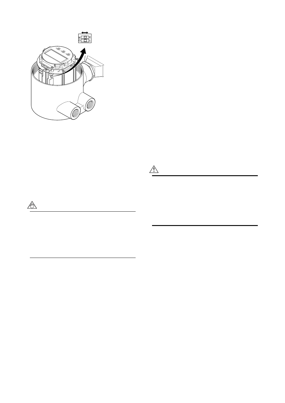
Switch 1
Low
High
Switch 2
Enable
Protect
F0520.EPS
2
← Burnout setting switch
1
← Write protect setting switch
Figure 5.5.1
Switch Configuration
5.5.2
Setting of Write Protect Switch
By setting the write protect function to “Protect” it is
possible to prevent the overwriting of parameters.
Write protection can be carried out using either the
hardware switch on the CPU board (i.e., Switch 2) or
software parameter settings. If either of these items is
set to “Protect,” the overwriting of parameters will be
prohibited.
NOTE
• If the hardware switch is set to “Protect,” it will
not be possible to overwrite parameters;
furthermore, this condition will be maintained
until the switch is set to “Enable.”
• In the case of Fieldbus communication type,
write protect setting switch is always be set as
“Enable”.
For more details regarding usage of the write protect
function and the software’s parameter switches, refer to
“Chapter 6: Parameter Description” in the user’s
manual of the AXF Integral Flowmeter [Software
Edition] (IM 01E20C02-01E).
5.6 Regular Inspection
Items
(1) Inspection of moisture-proofing inside the
terminal box: Once/year
(2) Retightening of piping joint screws: About
twice/year
(3) Inspection of electrodes and lining (in
case of adhesive and/or abrasive fluids,
etc.)
Determine the period of regular inspection as
necessary.
5.7 Excitation Coil and
Insulation Resis-
tance Check (Remote
Flowtube Only)
WARNING
• Before checking of the excitation coil and the
insulation resistance, be sure that the power
supply for AXFA11 or the AXFA14 converter
has been turned off.
• Before checking, be sure to disconnect the
cables from the terminals of the remote
flowtube.
(1) Excitation Coil Check (Remote Flowtube
Only)
Check that there is continuity between terminals EX1
and EX2 in the terminal box. If there is no continuity,
the coils may be broken and replacement or repair of
the flowtube is necessary. The coil resistance is
designed to be 150
⍀ or less. If it is not, this may be
an abnormal condition. Consult Yokogawa’s sales or
service offices.
(2) Insulation Resistance Check (Remote
Flowtube Only)
Check the insulation resistances in the terminal box in
accordance with the tables below. If any of them falls
below the values listed in the tables, consult
Yokogawa’s sales or service offices for investigation.
If the insulation resistance cannot be restored, replace-
ment or repair of the flowtube is needed. In case of
submersible type flowmeters, undo the wiring connec-
tion on the converter side and measure resistance at the
cable terminals.