Yokogawa ADMAG AXF User Manual
Page 75
IM 01E20D01-01E
6-13
6. OUTLINE
English Units (Size: in., Flow rate: GPM)
0 to Min. Span Flow Rate
(0.33ft/s)
0 to Max. Span Flow Rate
(33ft/s)
0 to 0.0078 GPM
0.1
0 to 0.7780 GPM
0 to 0.0312
0.2
0 to 3.112
0 to 0.1245
0.4
0 to 12.44
0 to 0.1946
0.5
0 to 19.45
0 to 0.7781
1.0
0 to 77.80
0 to 1.216
1.25
0 to 121.5
0 to 1.751
1.5
0 to 175.0
0 to 3.113
2.0
0 to 311.2
0 to 4.863
2.5
0 to 486.2
0 to 7.003
3.0
0 to 700.2
0 to 12.45
4.0
0 to 1,244
0 to 19.46
5.0
0 to 1,945
0 to 28.01
6.0
0 to 2,800
0 to 49.80
8.0
0 to 4,979
0 to 77.81
10
0 to 7,780
0 to 112.1
12
0 to 11,203
0 to 152.5
14
0 to 15,249
0 to 199.2
16
0 to 19,918
Size
(in.)
0 to 311.3
20
0 to 31,122
0 to 448.2
24
0 to 44,815
0 to 610.0
28
0 to 60,999
0 to 796.8
32
0 to 79,672
0 to 1,009
36
0 to 100,835
0 to 1,245
40
0 to 124,488
T24.EPS
0 to Min. Span Flow Rate
(1.0ft/s)
0 to Max. Span Flow Rate
(33ft/s)
0 to 4,519 GPM
44
0 to 150,630 GPM
0 to 5,378
48
0 to 179,262
0 to 6,807
54
0 to 226,879
0 to 8,403
60
0 to 280,098
0 to 9,561
64
0 to 318,689
0 to 12,101
72
0 to 403,341
0 to 14,939
80
0 to 497,952
0 to 18,076
88
0 to 602,522
0 to 21,512
96
0 to 717,051
0 to 25,247
104
0 to 841,540
Size
(in.)
T24-1.EPS
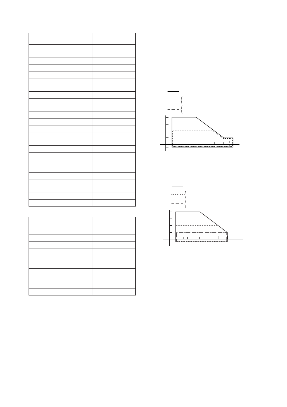
Fluid Temperature and Pressure:
Note *1 The following figures show maximum allowable
fluid pressure for the flowtube. Further fluid
pressure should also be limitted according to
flange rating.
*2 For fluid temperature of the explosion proof type,
refer to descriptions of “HAZARDOUS AREA
CLASSIFICATION”.
PFA Lining (*1)
General-Purpose Use, Submersible Type, Explosion
proof Type, Remote Flowtube (electrode structure
code 1: Non-replaceable electrode)
Pressure
MPa (psi)
4 (580)
2 (290)
1 (145)
– 0.1 (–14.5)
– 40
(–40)
40
(104)
100
(212)
160
(320)
Temperature
°C (°F)
130
(266)
2.5 to 50 mm (0.1 to 2.0 in.) (flange type, wafer type)
65 to 200 mm (2.5 to 8.0 in.) (flange type, wafer type)
250, 300 mm (10, 12 in.) (flange type)
250, 300 mm (10, 12 in.) (wafer type)
350, 400 mm (14, 16 in.) (flange type)
0
(32)
–10
(14)
F18-1.EPS
150
(302)
*1
General-Purpose Use and Explosion proof Type,
Integral Flowmeter (electrode structure code 1: Non-
replaceable electrode)
Pressure
MPa (psi)
4 (580)
2 (290)
1 (145)
– 0.1 (–14.5)
– 40
(– 40)
40
(104)
100
(212)
Temperature
°C (°F)
130
(266)
0
(32)
–10
(14)
2.5 to 50 mm (0.1 to 2.0 in.) (flange type, wafer type)
65 to 200 mm (2.5 to 8.0 in.) (flange type, wafer type)
250, 300 mm (10, 12 in.) (flange type)
250, 300 mm (10, 12 in.) (wafer type)
350, 400 mm (14, 16 in.) (flange type)
F18-2.EPS
*1
*1:
For wafer types of 32 mm to 300 mm(1.25 to 12 in.), and
for carbon steel flange types (process connection code:
C
**
) of 50 to 400 mm (2.0 to 16 in.), the minimum tem-
perature is –10
°C (14°F).
*2:
For fluid temperature of the explosion proof type, refer
to descriptions of “HAZARDOUS AREA CLASSIFI-
CATION”.