5 cable connection rtd terminal box side, Removing shielded cable with cable gland, Removing shielded cable for conduit use – Yokogawa EJX930A User Manual
Page 45: External temperature input code: -b, -c, -d) -8, Cable connection rtd terminal box side -8, Caution
<7. Wiring>
7-8
IM 01C25R01-01E
7.6.3 Removing Shielded Cable with Cable
Gland (External temperature input
code: -1, -2, -3, and -4)
(1) By pulling out the string attached to the
connector, carefully unplug the connector from
the transmitter’s connecting port.
(2) In the case of using 1/2NPT Type or M20
Type cable gland, remove the running coupler
and backnut assembly by turning the running
coupler.
In the case of using G1/2 Type cable gland,
loosen the lock nut screwed into the union
cover and remove the union cover. RTD cable
can be pulled out together with the packing box.
Loosen the clamp nut and the gland if
necessary.
(3) Pull the RTD cable out carefully.
(4) In the case of 1/2NPT Type or M20 Type cable
gland, remove the entry from the RTD electrical
connection by turning the entry.
In the case of G1/2 Type cable gland, loosen
the lock nut screwed into the adapter body and
remove the adapter body.
NOTE
In the case of G1/2 Type cable gland, remove
the rubber packing, washer, gland, clamp ring,
clamp nut, union coupling and union cover from
the opposite side of RTD connector in order to
take out the cable gland from the RTD cable.
7.6.4 Removing Shielded Cable for
Conduit Use (External temperature
input code: -B, -C, -D)
(1) By pulling out the string attached to the
connector, slowly unplug the connector from the
transmitter's connecting port.
(2) Remove the conduit from the RTD electrical
connection.
(3) Pull the RTD cable out through the RTD
electrical connection.
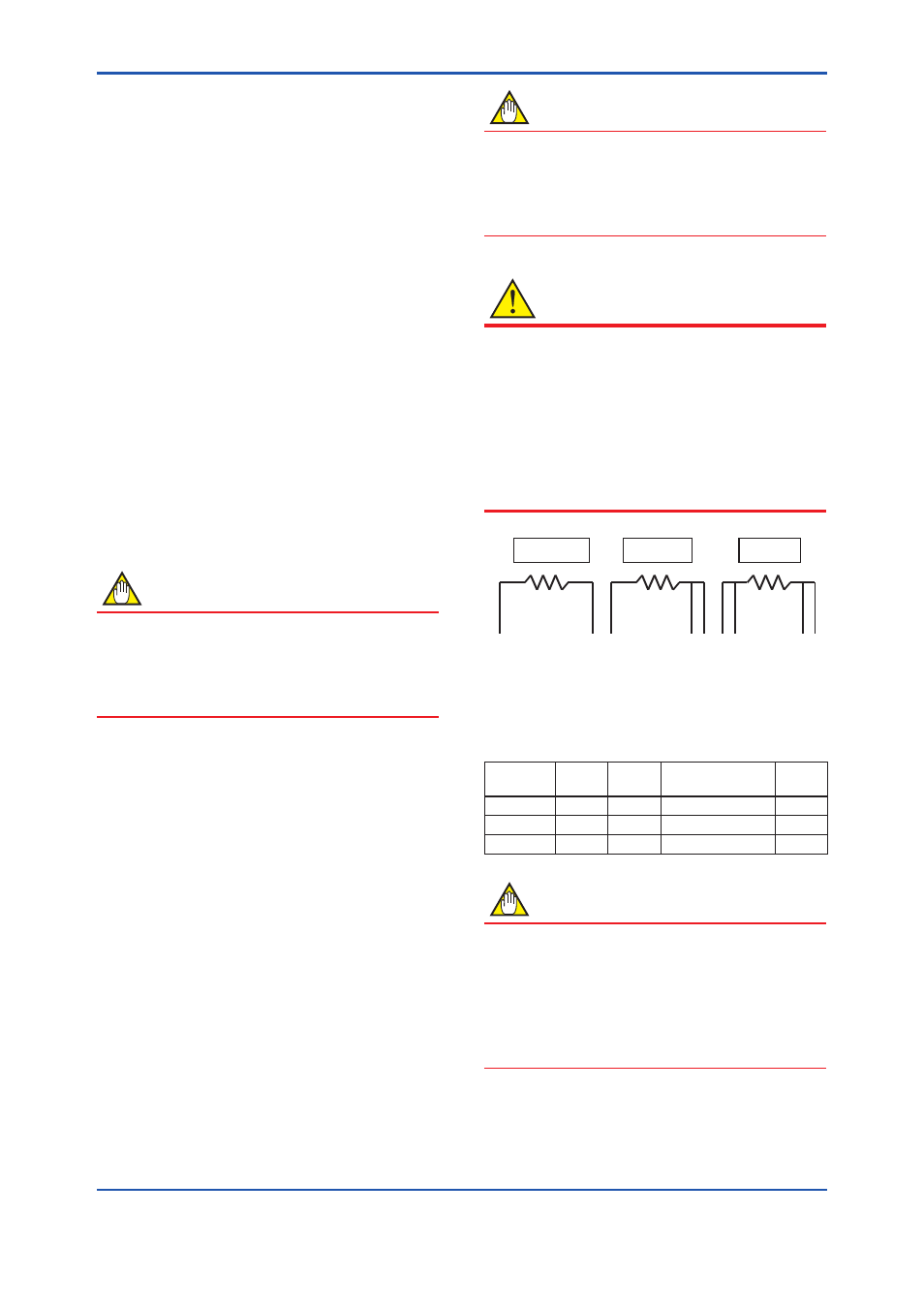
7.6.5 Cable Connection RTD Terminal Box
Side
EJX multivariable transmitter RTD I/F is for 3-wire
Type RTD, Pt100.
Heed the following when wiring an RTD of the 2- or
4-wire type.
NOTE
Please note that a temperature error will occur
when you use a 2-wire RTD because of wiring
resistance.
Please do not ground the shield on the RTD side
of the cable.
CAUTION
Please use only the cables provided with this
instrument.
When wiring, be sure not to damage the cable's
insulation or its core.
All the cable cores must have sufficient insulation
around them.
Do not let the signal line contact the shield line.
Do not allow the shield line or the signal line to
come the earth potential voltage.
2-Wire
3-Wire
4-Wire
A
B A
B b A
B b
a
F0723.ai
Figure 7.11 The Method of Wiring for the RTD Side
Table 7.1
The Method of Wiring for the RTD Side
RTD Terminal
RTD
Terminal
A
a
B
b
2-Wire
White
–
Blue1 and Blue2
–
3-Wire
White
–
Blue1
Blue2
4-Wire
White
open
Blue1
Blue2
NOTE
The color display in the table shows the white
line of the cable.
The cable color could change depending on the
cable type.
Blue1 and blue2 allow changing places.
For 2-wire Type, connect either which is blue1 or
blue2, and give other side as OPEN.