Wiring, 1 wiring precautions, 2 selecting the wiring materials – Yokogawa EJX930A User Manual
Page 38: 3 types of output, Wiring -1, Wiring precautions -1, Selecting the wiring materials -1, Types of output -1, 1 wiring precautions important
<7. Wiring>
7-1
IM 01C25R01-01E
7. Wiring
7.1 Wiring Precautions
IMPORTANT
• The information in the sections from 7.2
throught 7.5 (except for 7.5.2) is specific to
HART protocol type. Refer to IM01C25R03-
01E for F
OUNDATION
Fieldbus protocol
type or IM 01C25R05-01EN for Modbus
Communication Type.
• Lay wiring as far as possible from electrical
noise sources such as large capacity
transformers, motors, and power supplies.
• Remove the electrical connection dust cap
before wiring.
• All threaded parts must be treated with
waterproofing sealant. (A non-hardening
silicone group sealant is recommended.)
• To prevent noise pickup, do not pass signal
and power cables through the same ducts.
• Explosion-protected instruments must
be wired in accordance with specific
requirements (and, in certain countries,
legal regulations) in order to preserve the
effectiveness of their explosion-protected
features.
• The terminal box cover is locked by an
Allen head bolt (a shrouding bolt) on ATEX
flameproof type transmitters. When the
shrouding bolt is driven clockwise using
an Allen wrench, it goes in. The cover lock
can then be released and the cover can
be opened by hand. See subsection 8.4
“Disassembly and Reassembly” for details.
• Plug and seal an unused conduit connection.
• Do not turn on power until all wirings
including RTD finished.
7.2 Selecting the Wiring
Materials
(a) Use stranded leadwires or cables which are
the same as or better than 600 V grade PVC
insulated wire or its equivalent.
(b) Use shielded wires in areas that are susceptible
to electrical noise.
(c) In areas with higher or lower ambient
temperatures, use appropriate wires or cables.
(d) In environment where oils, solvents, corrosive
gases or liquids may be present, use wires or
cables that are resistant to such substances.
(e) It is recommended that crimp-on solderless
terminal lugs (for 4 mm screws) with insulating
sleeves be used for leadwire ends.
7.3 Types of Output
Table 7.2 shows the wiring example according to
the output types.
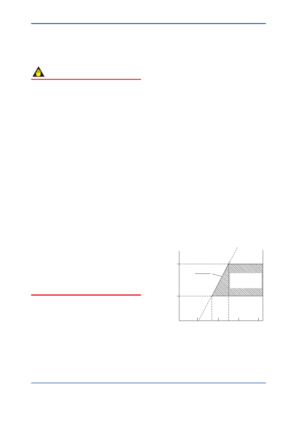
(1) Analog Output (4 to 20 mA DC)
This instruments uses the same two wires for both,
the signal and power supply. A DC power supply is
required in a transmission loop. The total leadwire
resistance including the instrument load and power
distributor (supplied by the user) must conform to
a value in the permissible load resistance range.
Refer to Figure below.
F0701.ai
E-10.5
0.0244
(Ω)
Power supply voltage E (V DC)
600
250
R
10.5
16.6
25.2
42
External
load
resistance
Digital
Communication
range
R=
Figure 7.1
Relation between Power Supply
Voltage and Load Resistance (4 to 20
mA DC Output)