Important – Yokogawa EJX930A User Manual
Page 16
<2. About the EJX Multivariable Transmitter>
2-8
IM 01C25R01-01E
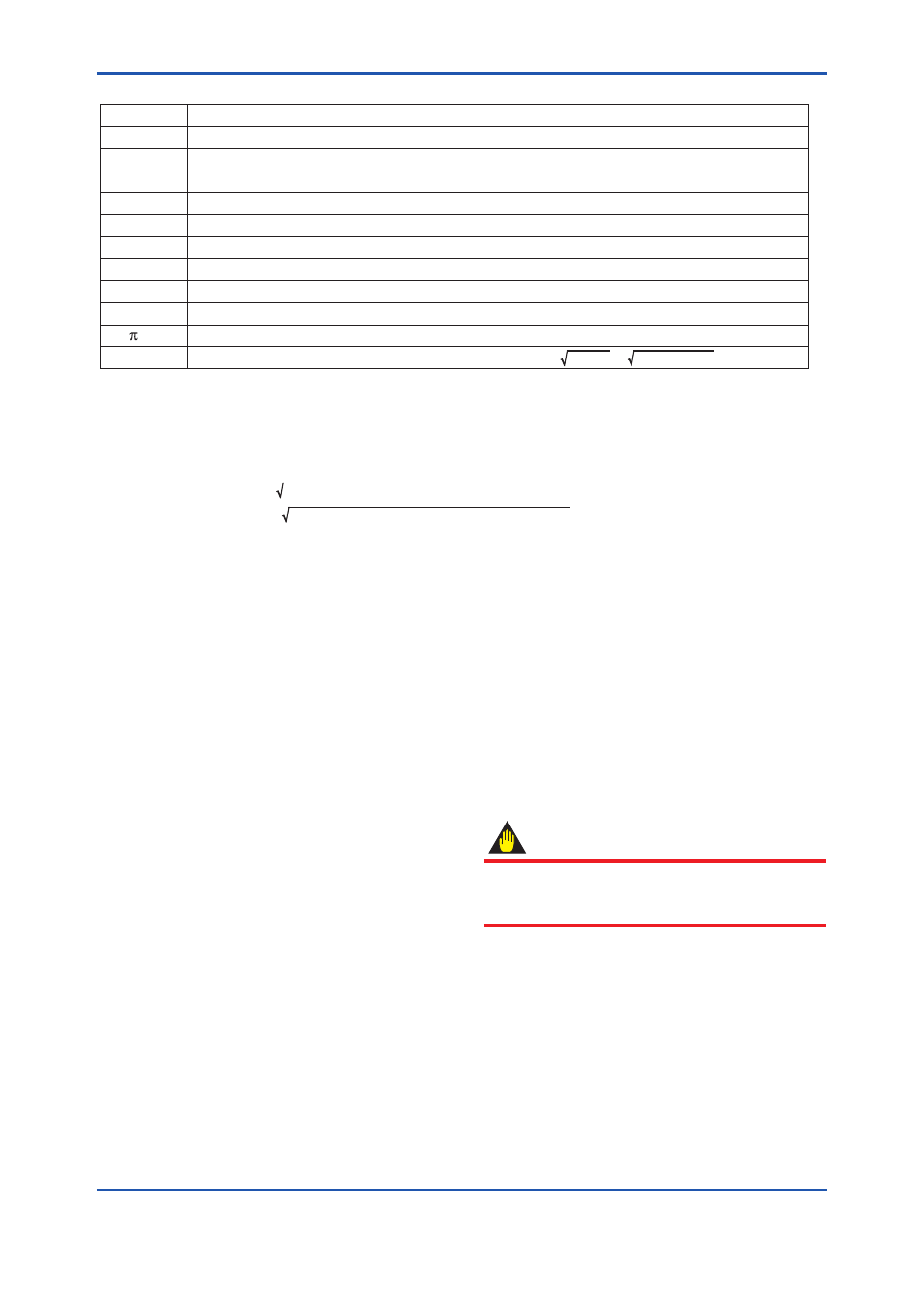
Table 2.8
Flow Parameter of Example
T0203.ai
C
ε
β
d
D
ρb
Tb
SPb
K
/4
Nc
Symbol
0.6043
0.984
0.6
0.03162 m
0.0527 m
1.250380 kg/m
3
273.15 K(0 degC)
101.325 kPa abs
1
0.7853982
31.62278
Value
Discharge coefficient Orifice Corner Taps [ISO5167-1 1991] ReD 1×10
6
Expansion factor β=0.6, ∆ρ=50,000 Pa, SP=1,000,000 Pa abs, κ=1.399502
Diameter ratio
Bore of orifice
Pipe diameter
Base Density on Tb, SPb Condition (NITROGEN 101,325 Pa abs 273.15 K)
Reference temperature unit: K
Reference static pressure unit: kPa abs
Compressibility factor
Unit convert factor when DP unit is kPa kPa/Pa = 1000Pa / 1Pa =31.62278
Description
Example 3: Calculation of Qm
Δp = 50kPa, SP = 500kPa abs, T = 293.15K
Qm(kg/s) = Kfactor × ∆p × (Tb / T) × (SP / SPb)
= 0.02503 Ч 50 Ч (273.15 / 293.15) Ч (500 / 101.325)
= 0.3795 (kg/s)
Method 2. Calculating the Kfactor by means of the flow condition.
Flow condition; DP, SP, SPb, T, Tb, and TempK1
(1) Selection of the flow equation
Select a desired operational expression
according to the fluid type and the flow unit
category shown in Table 2.1.
(2) Confirming the units
The unit to be used in the flow calculation is as
follows.
Static Pressure : kPa abs
Temperature : K
Regardless of the actual setting of the unit for
these items in the transmitter, the above units
are used for calculation.
The flow and the differential pressure are
calculated using the unit set to the transmitter.
(3) Preparation of parameters for calculation
All parameters use the units which are shown
at (2).
(4) Calculation of the Kfactor
Calculate the Kfactor by using the parameters
prepared at (3) and flow expression selected at
(1).
(5) Downloading flow parameter to transmitter.
Input Kfactor, Tb, SPb, and TempK1(liquid)
to the transmitter by a communication tool or
EJXMVTool.
IMPORTANT
If either the setting of flow unit or differential
pressure unit is changed, Kfactor must be
recalculated.