4 swapping the high/low-pressure side connection, 1 rotating pressure-detector section 180, 2 using the communicator – Yokogawa EJX930A User Manual
Page 32: Rotating pressure-detector section 180° -3, Using the communicator -3, 4 swapping the high/low- pressure side connection, Important
<5. Installation>
5-3
IM 01C25R01-01E
5.4 Swapping the High/Low-
pressure Side Connection
5.4.1 Rotating Pressure-detector Section
180°
This procedure can be applied only to a transmitter
with a vertical impulse piping type.
The procedure below can be used to turn the
pressure detector assembly 180°. Perform
this operation in a maintenance shop with the
necessary tools laid out and ready for use, and then
install the transmitter in the field after making the
change.
1) Use an Allen wrench (JIS B4648, nominal 2.5
mm) to remove the two setscrews at the joint
between the pressure-detector section and
transmitter section.
2) Leaving the transmitter section in position,
rotate the pressure-detector section 180°.
3) Tighten the two setscrews to fix the pressure-
detector section and transmitter section
together (at a torque of 1.5 N·m).
Reposition the process connector and drain
(vent) plugs to the opposite side as described in
subsection 4.3.
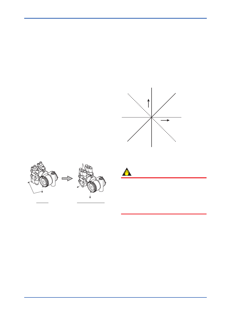
F0505.ai
Process connector
Setscrew
Before
After rotating 180°
Figure 5.5
Before and After Modification
5.4.2 Using the Communicator
With a communicator, you can change which
process connection is used as the high-pressure
side without mechanically rotating the pressure-
detector section 180 as described in subsection
5.4.1. To change, call parameter ‘H/L swap’ for
HART Communication and select REVERSE (right
side: low pressure; left side: high pressure) or select
NORMAL to change back to normal (right side:
high pressure; left side: low pressure). For other
communication type except HART Communication
Type, refer to each communication manuals.
Output
Input
NORMAL
REVERSE
F0506.ai
Figure 5.6
Input/Output Relationship
IMPORTANT
Since the H/L label plate on the capsule
assembly will remain unchanged, use this
function only when you cannot switch the
impulse piping. If the ‘H/L SWAP’ parameter
setting is changed, the input/output relationship
is reversed as shown in figure 5.6; be sure this is
understood by all.