2 routing the impulse piping, Routing the impulse piping -2 – Yokogawa EJX930A User Manual
Page 35
<6. Installing Impulse Piping>
6-2
IM 01C25R01-01E
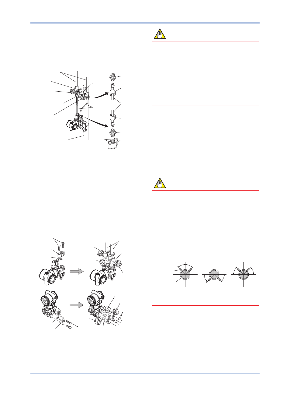
4) Now tighten the nuts and bolts securely in the
following sequence:
Process connector bolts → transmitter-end ball
head lock nuts → 3-valve manifold ball head
lock nuts → 3-valve manifold mounting bracket
U-bolt nuts
F0602.ai
Nipple
Nipple
Process
connector
Ball head
lock nut
Pipe
Ball head
lock nut
Process
connector bolts
50 mm(2-inch) pipe
Pipes
3-valve
manifold
Impulse piping
Vent plug
(optional)
Stop valve
(low pressure side)
Equalizing valve
(balancing)
Stop valve
(high pressure side)
Figure 6.2
3-Valve Manifold (Pipe-Mounting Type)
Direct-Mounting Type 3-Valve Manifold
(Figure 6.3)
1) Mount the 3-valve manifold on the transmitter.
(When mounting, use the two gaskets and the
four bolts provided with the 3-valve manifold.
Tighten the bolts evenly.)
2) Mount the process connectors and gaskets
on the top of the 3-valve manifold (the side on
which the impulse piping will be connected).
F0603.ai
Bolts
Process
connector
Gasket
Gasket
Process
connector
Bolts
Stop valve
Stop valve
3-valve
manifold
3-valve
manifold
Equalizing valve
Equalizing
valve
Stop valve
Impulse
piping
Impulse
piping
Stop valve
Figure 6.3
3-Valve Manifold (Direct-Mounting
Type)
NOTE
After completing the connection of the transmitter
and 3-valve manifold, be sure to CLOSE the low
pressure and high pressure stop valves, OPEN
the equalizing valve, and leave the manifold with
the equalizing valve OPEN.
You must do this in order to avoid overloading
the transmitter from either the high or the low
pressure side when beginning operation.
This instruction must also be followed as part of
the startup procedure (chapter 8.)
6.1.2 Routing the Impulse Piping
(1) Process Pressure Tap Angles
If condensate, gas, sediment or other extraneous
material in the process piping gets into the impulse
piping, pressure measurement errors may result. To
prevent such problems, the process pressure taps
must be angled as shown in figure 6.4 according to
the kind of fluid being measured.
NOTE
• If the process fluid is a gas, the taps must be
vertical or within 45° either side of vertical.
• If the process fluid is a liquid, the taps must
be horizontal or below horizontal, but not
more than 45° below horizontal.
• If the process fluid is steam or other
condensing vapor, the taps must be
horizontal or above horizontal, but not more
than 45° above horizontal.
[Gas]
Pressure
taps
Process
piping
[Steam]
[Liquid]
45°
45°
45°
45°
45°
45°
F0604.ai
Figure 6.4
Process Pressure Tap Angle (For
Horizontal Piping)