Caution, 1/2npt type m20 type, 5) align the running coupler on the entry – Yokogawa EJX930A User Manual
Page 42: Wiring, Protection cap connecting port
<7. Wiring>
7-5
IM 01C25R01-01E
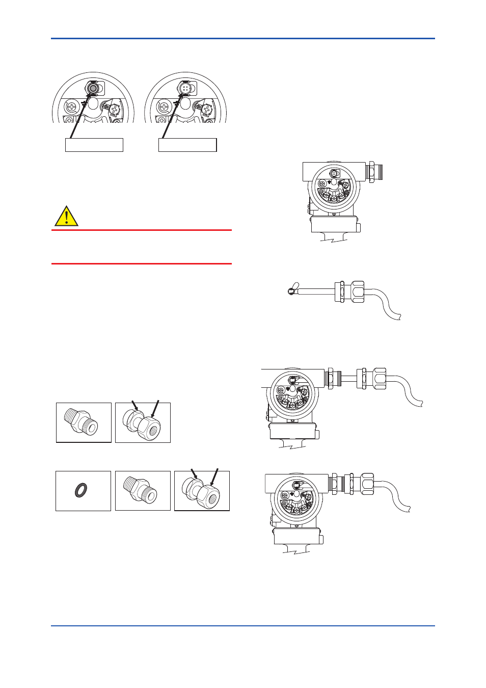
• Magnified view of the RTD connector in the
transmitter's terminal box.
SUPPL
Y
PULSE
CHECK
ALARM
SUPPL
Y
PULSE
CHECK
ALARM
Protection Cap
Connecting Port
F0714.ai
The RTD cable connecting port is covered with
a cap to keep out dust. The cap should not be
removed until you are ready to install the cable.
CAUTION
Input/output signal is non-isolated.
Do not turn on power supply until you complete
all the wiring work.
In the case of electrical connection code 2
(1/2NPT female) or 4 (M20 female).
• Components for the cable gland
The cable gland assembly consists of an entry,
seal, running coupler, and backnut. Confirm that
the seal is attached inside the entry and that the
thread size of the cable gland is the same as
that for the RTD electrical connection.
F0715.ai
1/2NPT Type
M20 Type
Gasket
Entry with Seal
Running
Coupler
Backnut
Entry with Seal
Running
Coupler
Backnut
Procedure
(1) Disassemble the cable gland: loosen the
running coupler to separate the backnut from
the entry.
(2) Remove the protection cap over the transmitter
electrical connection and install the entry on the
electrical connection. Note that a non-hardening
sealant should be applied to the threads for a
1/2 NPT connection and a gasket should be
used for an M20 connection.
Y
L
P
P
U
S
ESL
UP
K
C
E
H
C
M
R
A
L
A
F0716.ai
(3) Pass the RTD cable through the running
coupler and backnut assembly.
F0717.ai
(4) Insert the RTD cable and firmly plug its
connector into the connecting port in the
transmitter's terminal box.
YL
P
P
U
S
ESL
UP
K
C
E
H
C MR
A
L
A
F0718.ai
(5) Align the running coupler on the entry.
YL
P
P
U
S
ESL
UP
K
C
E
H
C MR
A
L
A
F0719.ai