1 zero point adjustment, 2 ident number configuration, 3 bus address configuration – Yokogawa EJX115A User Manual
Page 46: Zero point adjustment -5, Ident number configuration -5, Bus address configuration -5
<7. In-Process Operation>
7-5
IM 01C25T04-01EN
F0705.ai
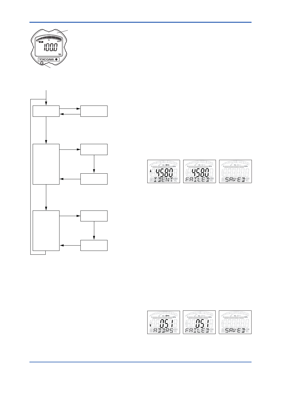
Integral indicator
Local operation switch
(Push-button)
Note 1: Use a thin bar which has a
blunt tip, e.g., a hexagonal
wrench, to press the Local
operation switch.
Note 2: The switch is located in
either lower right or lower left
portion of the LCD indicator.
Figure 7.5
Local Operation Switch
Display the
process value
Display the
Ident number
Display the
Address
Write
Press the button
below the LCD display
(to request setting)
Select the
Address
Write
Press the button
below the LCD display
(to request writing)
Select the
Ident number
Adjust the zero
point
Automatic
transition
Turn the external
adjustment screw
Press the button
below the LCD display
(to change the screen)
Automatic
transition
Turn the external
adjustment screw
Press the button
below the LCD display
(to change the screen)
Turn the external
adjustment screw
F0706.ai
Figure 7.6
Setting flow of Local Operation
Interface
7.5.1 Zero Point Adjustment
While the process value screen is displayed, the
zero point can be adjusted by using the external
adjustment screw. The Local Operation (LOCAL_
OP_ENA) parameter can be used to enable or
disable the zero point adjustment with the external
adjustment screw. To use the external adjustment
screw, set the parameter to “Enabled” (default
setting is “Enabled”). For the setting procedure,
see subsection 5.2.1. Turn the external adjustment
screw with a flathead screwdriver to adjust
the value to zero. Turning the screw clockwise
increases the output and turning it counterclockwise
decreases the output. Zero point adjustment can be
performed with a resolution of 0.01% of the setting
range.
7.5.2 Ident Number Configuration
When the push button below the LCD display
is pressed while the process value screen is
displayed, the screen changes to the Ident number
setting screen. A four-digit value is displayed in the
middle of the screen and “IDENT” is shown below
it. Turn the external adjustment screw to select a
desired number and press the button below the
LCD display to set the number. When the number is
successfully set, “SAVED” will appear at the bottom
of the screen. If the setting is impossible or fails,
“FAILED” will appear. In this case, turn the external
adjustment screw to select a number to be set and
press the button below the LCD display again to set
the number.
F0707.ai
P SP
T
F
P SP
T
F
P SP
T
F
Figure 7.7
Setting screen of Ident Number
Configuration
7.5.3 Bus Address Configuration
When the push button below the LCD display
on the screen is pressed while the Ident number
setting screen is displayed, the screen changes
to the Bus Address setting screen. A number from
0 to 125 is displayed in the middle of the screen
(the default is 126), and “ADDRS” is shown at the
bottom of the screen. Turn the external adjustment
screw to select an address to be set and press the
button below the LCD display to set the address.
When the address is successfully set, “SAVED” will
appear at the bottom of the screen and restart. If the
setting is impossible or fails, “FAILED” will appear.
In this case, turn the external adjustment screw
to select a number to be set and press the button
below the LCD display again to set the address.
F0708.ai
P SP
T
F
P SP
T
F
P SP
T
F
Figure 7.8
Setting screen of Bus Address
Configuration