2 target mode, 3 basic parameter of sensor transducer block, 3 lcd transducer block – Yokogawa EJX115A User Manual
Page 35: 1 outline of the functions, 3 display contents of the integral indicator, Target mode -2, Basic parameter of sensor transducer block -2, Lcd transducer block -2 6.3.1, Outline of the functions -2, Display contents of the integral indicator -2
<6. Explanation of Basic Items>
6-2
IM 01C25T04-01EN
6.2.2 Target Mode
The Block modes permitted for the SENSOR
transducer block are Automatic (Auto) and Out of
Service (O/S). The mode must be set to Auto under
normal operating conditions, and to O/S when
making changes to an important parameter. For
parameters that can only be changed in the Auto
and O/S modes, refer to the parameter list for the
SENSOR Transducer block.
6.2.3 Basic Parameter of SENSOR
Transducer Block
Scale In (SCALE_IN)
Scale In is the input conversion of pressure using
high and low scale. The related unit is the pressure
unit. Refer to 5.1.2 for configurations.
Primary Value (PRIMARY_VALUE)
This parameter contains the measured value and
status available to the function block.
Calculate Coefficient (CALCULATE_COEF)
Coefficient for calculating Calculate Value
(CALCULATE_VALUE). Calculate Coefficient can
be considered as Kfactor for flow rate calculation.
Refer to Subsection 5.3.4 for Kfactor calculation.
Calculated Value (CALUCULATE_VALUE)
Calculation result of (Primary Value) × (Calculate
Coefficient)
Calculated Value Unit (CALCULATE_UNIT)
Unit for Calculate Value.
Characterization Type (LIN_TYPE)
Characterization type of output signal can be select
from Linear, user defind (table) or Square root. user
defind (table) is used to compensate the output for
non-linear applications. For the measured pressure,
a maximum of 31 coordinates can be specified
between 0 – 100%. Please refer 5.1.3 to for more
information.
Low Flow Cut Off (LOW_FLOW_CUTOFF)
This is the point in percent of flow until the output
of the flow function is set to Zero. It is used for
suppressing low flow values. Refer to 5.3.1 for
detail.
6.3 LCD Transducer Block
6.3.1 Outline of the Functions
The LCD transducer block controls alarms and
measured values that are displayed on the integral
indicator. It displays not only OUT signals from the
AI blocks, but also I/O signals of the Installed blocks
on the integral indicator.
6.3.2 Target Mode
The Target modes permitted for the LCD transducer
block are Automatic (Auto) and Out of Service (O/
S). Settings can be changed in the AUTO mode for
this block, except the Block tag parameter.
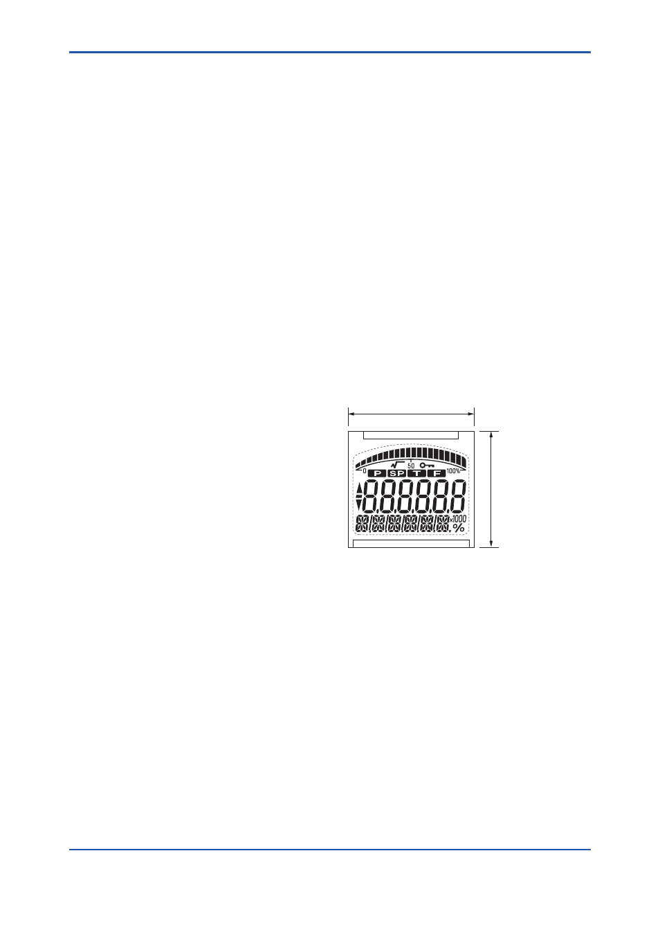
6.3.3 Display Contents of the Integral
Indicator
The components of the integral indicator are the bar
graph, the title field, the center field for numerical
values, the lower text field, and auxiliary characters.
The contents and meanings of these components
are as follows:
F0602.ai
40.000
37.000
Figure 6.2
Screen Display of the integral indicator