Yokogawa EJX115A User Manual
Page 32
<5. Parameter Setting>
5-12
IM 01C25T04-01EN
a. Display Selection
A cycle of up to four displays can be shown by
assigning variables to the parameters at
Display
Selection.
• Procedure to call up the display
DTM, EDD
Local Display → Display Selections →
Display Selection
b. Parameter Selection
At
Parameter Selection, select the variable that
will display on the integral indicator.
• Procedure to call up the display
DTM, EDD
Local Display → Display (1-4) Selections
→ Parameter Selection (1-4)
→ Display1
“on” or “off”
→ Display2
“on” or “off”
→ Display3
“on” or “off”
→ Display4
“on” or “off”
Set Parameter Selection 2, Parameter Selection
3 and Parameter Selection 4 in the same way if
necessary.
In addition to the above item, “Not used” is also
displayed as a selection item.
c. Information Selection
Information Selection parameter specifies
whether Display tag, Parameter, Unit or Status
should be displayed on bottom part of integral
indicator.
• Procedure to call up the display
DTM, EDD
Local Display → Display Selections
→ Information Selection
→ TAG
“on” or “off”
→ PARAMETER “on” or “off”
→ UNIT
“on” or “off”
→ STATUS
“on” or “off”
d. Display Tag
At
Display Tag parameter, user can set display tag
of up to 6 alphanumeric characters, slash (/) and
period (.).
• Procedure to call up the display
DTM, EDD
Local Display → Display (1-4) Setup →
Display Tag (1-4)
e. Unit Selection
Select whether unit to be displayed in the lower
text field should be automatically selected or
customized by user in parameter
Unit Selection.
Select “Auto” if you want to have unit chosen from
specified units and “Custom” for engineering unit
which you can input freely.
• Procedure to call up the display
DTM, EDD
Local Display → Display (1-4) Setup →
Unit Selection (1-4)
→ Auto
Select unit from the list
→ Custom
Input engineering unit by user
f. Display Unit
Display Unit parameter allows the engineering unit
to be displayed. Up to 6 alphanumeric characters
and one slash (/) and one period (.) can be input at
Display Unit; only the first six are displayed on the
integral indicator.
• Procedure to call up the display
DTM, EDD
Local Display → Display (1-4) Setup →
Display Unit (1-4)
Note that following symbols are not available.
# % & < > * : + - , ‘ ( )
The integral indicator shows “------“ when these
symbols or more than two slashes are entered.
g. Exponent Mode
User can change the position of decimal point
which is shown on the integral indicator. Select from
0, 1, 2, 3 or 4.
• Procedure to call up the display
DTM, EDD
Local Display → Display (1-4) Setup →
Exponent Mode (1-4)
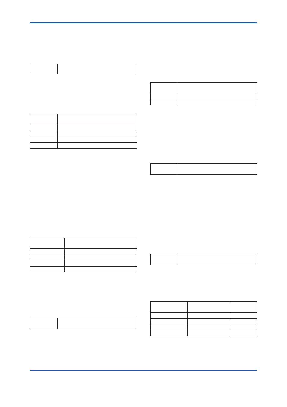
Example of exponent setting:
The LCD value for exponent setting when the actual
pressure value is 23.4568kPa and the decimal point
is selected ‘2’.
Corresponding
decimal point
Exponent
LCD value
(kPa)
2
Engineering Unit
23.46
2
Eng. Unit@1/10
2.35
2
Eng. Unit@1/100
0.23
2
Eng. Unit@1/1000
0.02