Important – Yokogawa EJX115A User Manual
Page 29
<5. Parameter Setting>
5-9
IM 01C25T04-01EN
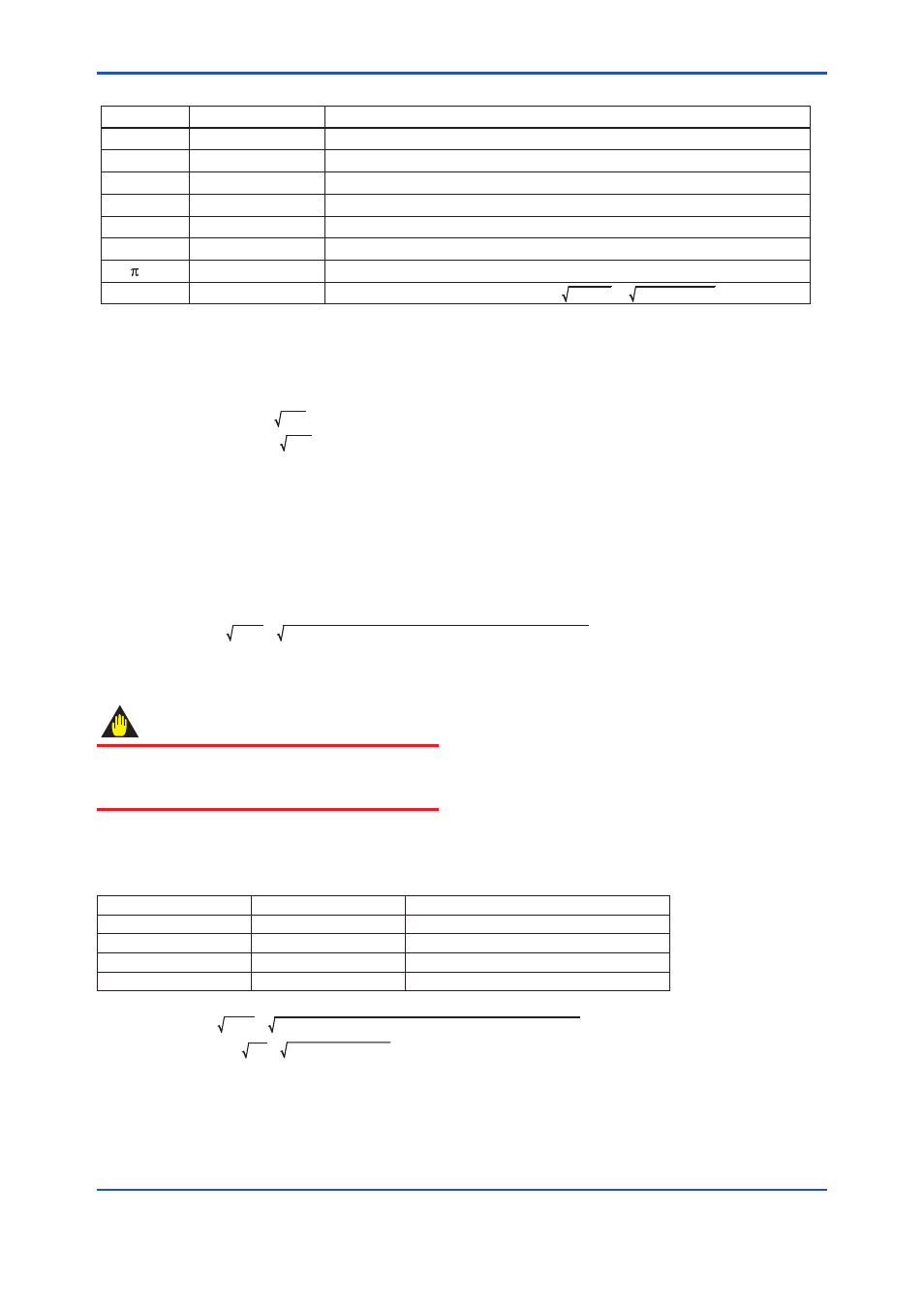
Table 5.6
Flow Parameter of Example
T0503.ai
C
ε
β
d
D
ρb
/4
Nc
Symbol
0.6043
0.984
0.6
0.03162 m
0.0527 m
1.250380 kg/m
3
0.7853982
31.62278
Value
Discharge coefficient Orifice Corner Taps [ISO5167-1 1991] ReD 1×10
6
Expansion factor β=0.6, ∆ρ=50,000 Pa, SP=1,000,000 Pa abs, κ=1.399502
Diameter ratio
Bore of orifice
Pipe diameter
Base Density on Tb, SPb Condition (NITROGEN 101,325 Pa abs 273.15 K)
Unit convert factor when DP unit is kPa kPa/Pa = 1000Pa / 1Pa =31.62278
Description
Example 3: Calculation of Qm
∆p = 50kPa,
Qm(kg/s) = Kfactor × ∆p
= 0.02503 × 50
= 0.1770 (kg/s)
Method 2. Calculating the Kfactor from differential pressure and flow rate in normal condition
(1) The flow rate and the differential pressure are calculated using the unit set to the transmitter.
(2) Calculation of the Kfactor
Calculate the Kfactor by using the flow rate and the differential pressure.
Kfactor can be calculated from equation shown in below.
Kfactor = [Qm / (∆p)] / [(ScaleOut_U − ScaleOut_L) + ScaleOut_L]
(3) Enter kfactor as shown in beginning of this section.
IMPORTANT
If either the setting of flow unit or differential
pressure unit is changed, Kfactor must be
recalculated.
Example: Kfactor Calculation
Table 5.7
Flow Condition Example
Symbol
Value
Description
Qm
0.3795 kg/s
Flow rate in normal condition
Δp
50 kPa
Differential pressure
ScaleOut_U
100 kPa
Upper valur of ScaleOut
ScaleOut_L
0 kPa
Lower value of ScaleOut
Kfactor = [Qm / (∆p)] / [(ScaleOut_U − ScaleOut_L) + ScaleOut_L]
= (0.3795 / 50) / [(100 − 0) + 0]
= 0.005367