3 signal characterizer, Signal characterizer -6 – Yokogawa EJX115A User Manual
Page 26
<5. Parameter Setting>
5-6
IM 01C25T04-01EN
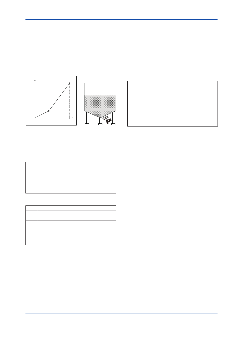
5.3.3 Signal Characterizer
Below is the example of performing the signal
characterizer as shown in Figure 5.2. Target Mode
of Sensor Transducer Block need to be changed
to Out of Service (O/S) before setting linearization
table. In order to use signal characterizer,
“User defined (table)” must be chosen for
Characterization Type. Refer to subsection 5.1.3 for
changing Characterization Type.
40%
100%
0%
20%
100%
Y
X
F0504.ai
Figure 5.2
<1> Configuration of new linearization table can be
performed in “Query Device” in “Device” menu
in top section of tool window.
• Procedure to call up the display
DTM
[Device] → Configuration →
Characterization → Table
Coordinate →
EDD
[Device] → Characterization →
Linearization →
→ Operation Mode Select the transaction of the user
defined table
Table 5.1
Operation Mode
Code
Description
0
Not initialized.
1
New operation characteristic, first value.
3
Last value, end of transmission, check table, or
swap the old curve with the new curve.
4
Delete point of table.
5
Insert point defined.
6
Replace point of table.
Select “1: New operation characteristic, first value”
for new operation.
<2> Enter Lower and Upper Scale In / Out value.
Refer to subsection 5.1.2 and 5.3.2 for
procedure. For this case, scales should be
entered shown as below.
Scale In: Lower Value
→
0
Scale In: Upper Value
→
100
Scale out: Lower Value
→
0
Scale unt: Upper Calue
→
100
<3> Enter Coordinate No. and X, Y value
• Procedure to call up the display
DTM
[Device] → Configuration →
Characterization → Table
Coordinate →
EDD
[Device] → Characterization →
Linearization →
→ Coordinate No.
Number of coordinate
→ X Y value couple
- X
Input value of linearization table
→ X Y value couple
- Y
Output value of linearization table
X_
i
=(PrV–ScaleIn_L)/(ScaleIn_U–ScaleIn_L)
Y_
i
=X_
i
×{(ScaleOut_U–ScaleOut_L)+ScaleOut_L}
(i=1 to 31)
PrV: Pressure Value
ScaleIn_L: Scale In:Lower Value
ScaleIn_U: Scale In:Upper Value
ScaleOut_L: Scale Out:Lower Value
ScaleOut_U: Scale Out:Upper Value
For this case, Coordinate No. and X/ Y values
should be entered shown as below.
Coordinate No.: 1
X Y value couple – X : 0.0
X Y value couple – Y : 0.0
Coordinate No.: 2
X Y value couple – X : 0.4
X Y value couple – Y : 0.2
Coordinate No.: 3
X Y value couple – X : 1.0
X Y value couple – Y : 1.0
<4> To definite linearization table, select Code: 3 in
Operation Mode shown in procedure <1> and
update linearization table.