Wiring the series 988, Input-to-output isolation, Power wiring – Watlow Series 988 User Manual
Page 14: Wiring
2.4
WATLOW Series 988 User’s Manual
Installation and Wiring, Chapter 2
Wiring
Wiring the Series 988
Wiring options depend on the model number and DIP switch settings.
Check the terminal designation stickers on either side of the controller
and compare your model number to those shown here and with the model
number breakdown on the
of this manual.
Input-to-output Isolation
The Series 988 uses optical isolation between the analog inputs and the
controller outputs/digital input. This isolation provides a 500VÅ (ac) bar-
rier to prevent ground loops when using grounded sensors and/or periph-
eral equipment.
Here is a breakdown of the isolation barriers:
• Analog inputs 1 and 2 are grouped together.
• Outputs 1 through 4 and the standard event input are grouped together.
This does not apply to Output 4 when configured as communications.
• The digital communications output (4) is separate from the above
groups.
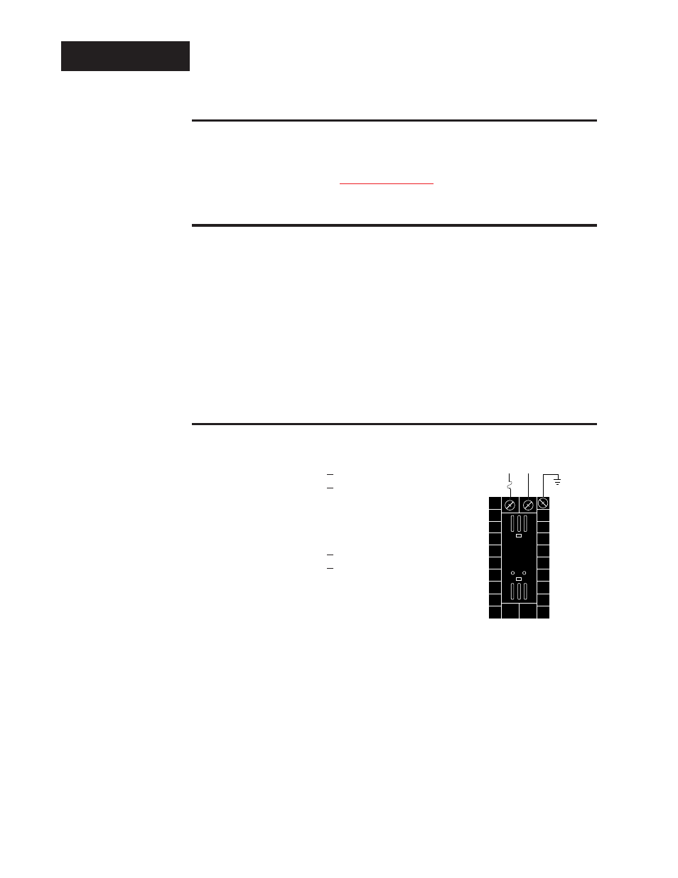
Power Wiring
100 to 240V
‡
‡
(ac/dc) nominal, (85 to 264 actual)
Vertical Package
98 8 _ - _ _ _ _ - _ _ _ _
Horizontal Package
98 9 _ - _ _ _ _ - _ _ _ _
24 to 28 V
‡
‡
(ac/dc) nominal, (20 to 30 actual)
Vertical Package
98 6 _ - _ _ _ _ - _ _ _ _
Horizontal Package
98 7 _ - _ _ _ _ - _ _ _ _
fuse
22
21
earth ground
11
L2
L1
+
-
∫
WARNING:
To avoid potential
electric shock, use
National Electric
Code (NEC) safety
practices when
wiring and connect-
ing this unit to a
power source and
to electrical sensors
or peripheral
devices. Failure to
do so could result
in injury or death.
˜
NOTE:
Input-to-output iso-
lation is defeated
when the external
signal conditioner
power supply is
used to power a
transmitter con-
nected to input 1 or
input 2.
Figure 2.4 -
Power wiring.