Chapter 2, Mount the controller, Wire and document the controller wiring – Watlow Series 988 User Manual
Page 11: Chapter 2 installation and wiring
WATLOW Series 988 User’s Manual
2.1
Installation and Wiring, Chapter 2
Chapter 2 Installation and Wiring
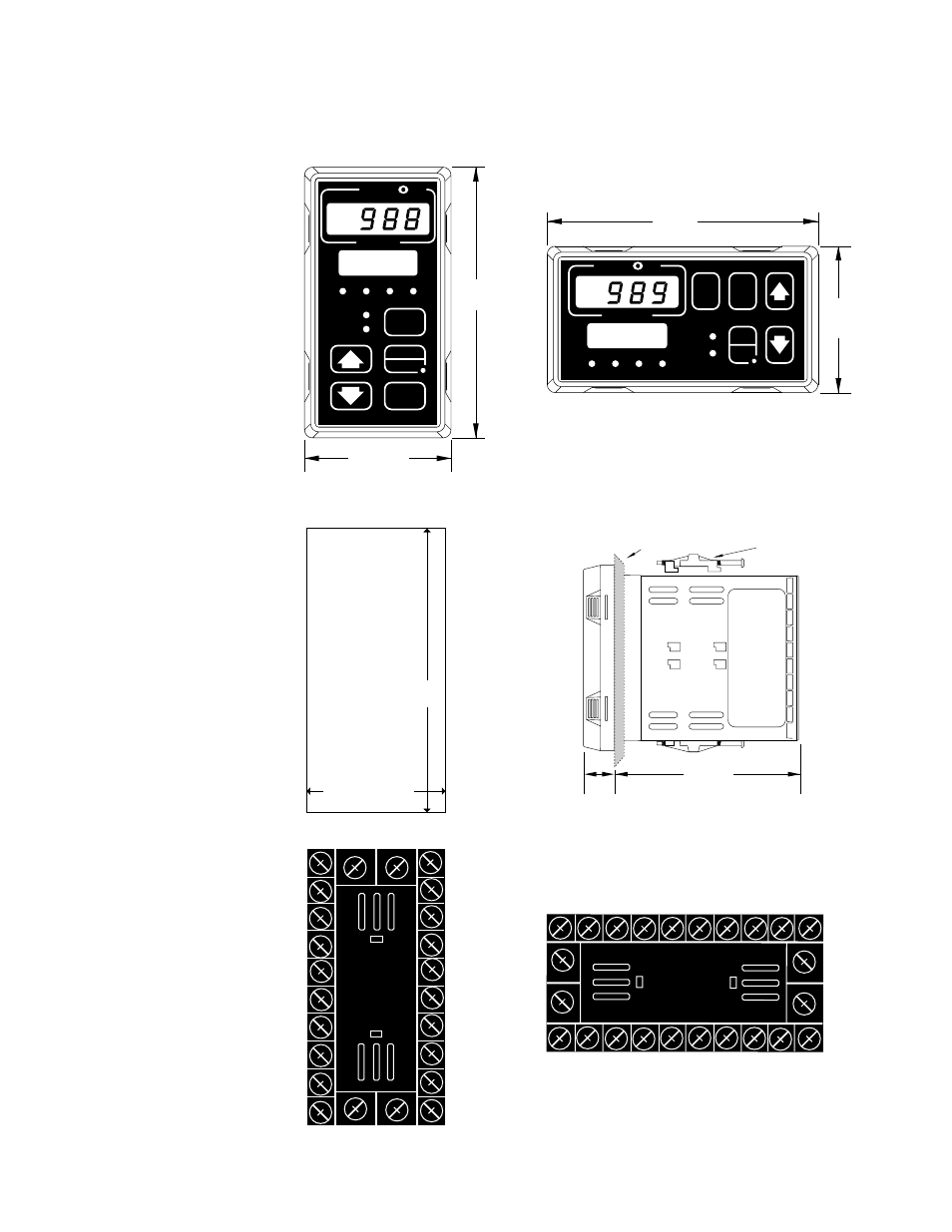
Panel Cutout
Maximum Panel
Thickness
0.38" (9.65mm)
3.62" + 0.03 -0.00
(92mm + 0.8)
1.77 + 0.02 -0.00
(45mm + 0.6)
4.03"
(102mm)
2.18"
(55 mm)
TL
W
WA
PROCESS
L1
L2
L3
L4
DEV
% OUT
DISPLAY
SERIES 988
MODE
AUTO
MAN
4.03"
(102mm)
2.18"
(55 mm)
TL
W
WA
PROCESS
L1
L2
L3
L4
DEV
% OUT
MODE
SERIES 989
DSPY
AUTO
MAN
Figure 2.1 -
Series 988 and
Series 989
dimensions and
terminal number
layout.
Panel
Adjustable
Mounting Bracket
4.06"
(103 mm)
0.68"
(17 mm)
˜
NOTE:
Adjustable mount-
ing brackets can be
side-mounted.
˜
NOTE:
Space panel
cutouts at least 1.66
inches (42.2mm)
apart.
˜
NOTE:
Holes can be cut in
the panel using a
Greenlee 1/8 DIN
Hydraulic Kit
#60068 (punch
#60069, die #60070).
12
13
14
15
16
17
18
19
3
4
5
6
7
8
9
11
22
21
1
20
23
10
24
2
12
13
14
15
16
17
18
19
2
3
4
5
6
7
8
9
11
22
21
1
20
24
23
10
- 12LS Controller (111 pages)
- 8LS Controller (140 pages)
- 8PID Controller (55 pages)
- Addendum to EZwarePlus (50 pages)
- ANASCAN (62 pages)
- ANASOFT (95 pages)
- ANAWIN 2 (154 pages)
- ANAWIN 3 (23 pages)
- Calibrating Watlow Series 988 Family Process Controls (19 pages)
- CAS (98 pages)
- CAS200 (124 pages)
- CLS (180 pages)
- CLS200 (251 pages)
- CLS200, MLS300 and CAS200 (92 pages)
- Control Console (12 pages)
- CPC400 (230 pages)
- DIN-A-MITE Style A (9 pages)
- DIN-A-MITE Style B (14 pages)
- DIN-A-MITE Style C (22 pages)
- DIN-A-MITE Style D (9 pages)
- DIN-Mount Adapter Instruction Sheet, Rev A (1 page)
- Dual DAC (4 pages)
- EM Gateway (28 pages)
- E-Safe Hybrid Relay Rev B (4 pages)
- E-SAFE II Hybrid Power Switch (4 pages)
- EZwarePlus Programming (264 pages)
- EZ-ZONE PM (111 pages)
- EZ-ZONE PM PID (125 pages)
- EZ-ZONE PM Express Limit (34 pages)
- EZ-ZONE PM Express (35 pages)
- EZ-ZONE PM Integrated Controller (181 pages)
- EZ-ZONE RM Limit Module Rev C (127 pages)
- EZ-ZONE RMA Modul (79 pages)
- EZ-ZONE RMC (236 pages)
- EZ-ZONE RME (124 pages)
- EZ-ZONE RMH (161 pages)
- EZ-ZONE RUI/Gateway (62 pages)
- EZ-ZONE RM-Scanner-Modul (140 pages)
- EZ-ZONE ST (97 pages)
- F4 External Event Board - Rev.B (2 pages)
- HG Series Mercury Displacement Relay (6 pages)
- LogicPro (296 pages)
- Mercury Relay or MDR Retrofit (13 pages)
- MICRODIN (24 pages)
- MICRODIN (106 pages)