Output, Step 3: output, Helpful references – Watlow Optimizing Your Process System with the Series 988 Controller User Manual
Page 61
Optimizing Your Process System with the WATLOW Series 988
How to Choose the Right 988 to Fit Your Application
7.4
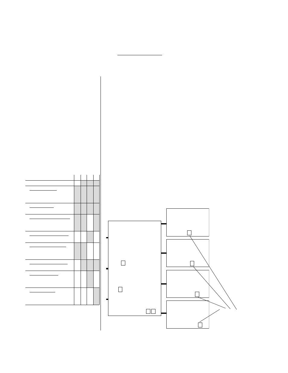
Outputs
1
2
3
4
A-none
solid-state relay
B-0.5A w RC suppression
K-0.5A w/o RC suppression
open collector
C-switched DC
electromechanical relay
D-form C, 5A w RC supp
E-form C, 5A w/o RC supp
electromechanical relay
J-form A or B, 5A w/o RC spp
universal process types
F-0-5VDC, 1-5VDC, 0-10VDC;
0-20mA, 4-20mA
transmitter power supply
T-5, 12, 20VDC @ 30 mA
process retransmit
M-0-20mA, 4-20mA
N-0-5VDC, 1-5VDC, 0-10VDC
communications
R-RS-232
S-EIA485, RS-422
Step 3: Output
A. List all the output devices in your process sketch
(Refer to your answer to 1F.).
B. List all of the parameters and specifications that
apply to each of the above items.
C. Output types must match the appropriate output
of the 988. Use the Output Chart on page 6.3 to
assign each output device to one of the 988’s out-
puts.
D. Use the information on your list to fill in the
output boxes in your photocopy of the worksheet
from page 7.10.
E. Make a sketch of your application on your photo-
copy of the worksheet. Make sure the appropriate
devices are connected to the appropriate inputs and
outputs.
Use the complete output table in
Chapter 6, Specifications.
Alarms and, transmitter power
supply are explained in Chapter
5, Other Features.
See the filled in worksheets in
Chapter 1, Test Drives.
HELPFUL REFERENCES
Fill in output devices
and codes from page
6.3.
Output #1
98_ _ - _ _
_ - _ _ _ _
Output #3
98_ _ - _ _ _ _ -
_ _ _
Output #2
98_ _ - _ _ _
- _ _ _ _
Output #4
98_ _ - _ _ _ _ - _
_ _
WATLOW
988
Key Features:
Software:
98 _
- _ _ _ _ - _ _ _ _
Power & Hardware:
98
_ - _ _ _ _ - _ _ _ _
Display colors:
98 _ _ - _ _ _ _ - _ _
_ __ __ - __ __ __ __
options available if shaded