Alarms, Standard features – Watlow Optimizing Your Process System with the Series 988 Controller User Manual
Page 42
Optimizing Your Process System with the WATLOW Series 988
Standard Features
5.2
Alarms
Overview
Outputs 2, 3 and 4 can be configured as
alarms. To configure an alarm the operator
makes several decisions. First we’ll show the
difference between a form A, B and C relay.
alarm is a deviation, process or rate alarm.
Selecting process 1
or deviation 1
references the input 1 value against the alarm 2
low
and alarm 2 high
settings.
Selecting process 2
or deviation 2
references the input 2 value against the alarm 2
low
and alarm 2 high
settings. Input
2 hardware must be connected and enabled.
Selecting rate
references the rate of
change of the input 1 value in degrees per
minute.
defines a negative rate and
defines a positive rate of change limit.
A process alarm sets an absolute process value
independent of the set point. When the process
exceeds that value an alarm occurs. The pro-
cess value is independent of the set point.
A deviation alarm alerts the operator when the
process strays too far from the set point. The
operator can enter both high and low alarm
settings referenced to the set point. A change in
set point causes a corresponding shift in the
deviation alarm. Low alarms are set at a nega-
tive deviation, and high alarms are set at a
positive deviation.
3-Hysteresis
This selects the switching hysteresis for the
alarm. Once an alarm has occurred it will not
clear until the process value is above the alarm-
low setting or below the alarm-high settings by
a margin equal to the hysteresis.
Example: An alarm starts when the process
value reaches the alarm high setting. The alarm
will not clear until it is below the high setting by
an amount equal to or greater than the alarm
hysteresis.
4-Latching
Alarms can be latching or non-latching. When
the alarm condition is removed, a non-latching
alarm automatically clears the alarm output
and alarm message, if one is present. You must
manually clear a latched alarm by pressing the
AUTO/MAN key once.
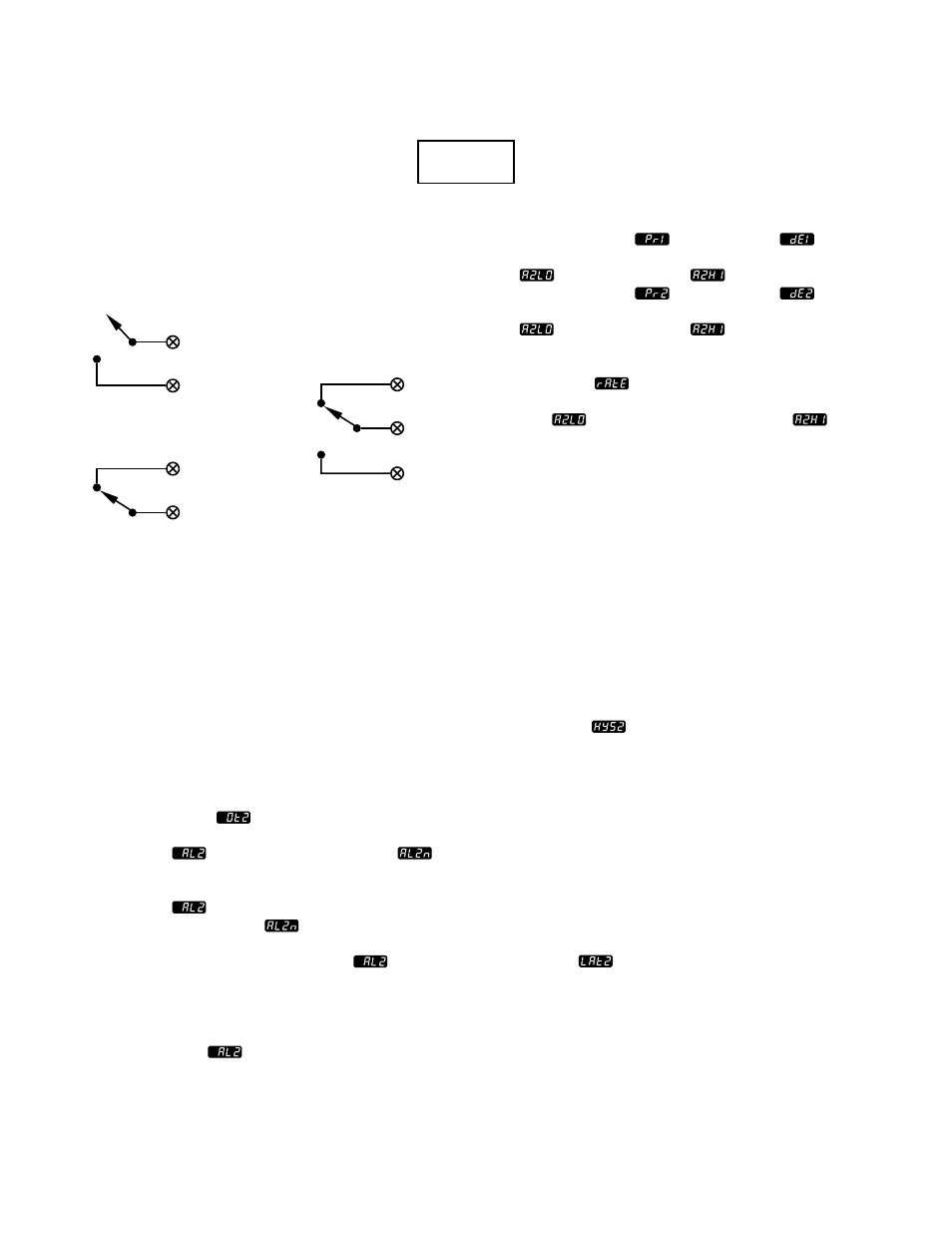
The relays are shown in the “shelf state,” with
no power applied. Note that the form C option
allows the operator to configure it as either a
form A or a form B output. For the purposes of
this discussion we will use the form C version,
available in outputs 2 and 4 (Output 3 is
selected, via a hardware jumper, as either a
form A output or a form B output).
You need to make five decisions to configure an
alarm output. In the following explanations
only output 2 will be configured:
1-Output Type
First, choose the type of alarm: either normally
energized
or normally de-energized
.
This means that when there is no alarm condi-
tion, the alarm output is energized if normally
energized
is selected and de-energized if
normally de-energized
is selected.
Example: With normally energized
se-
lected for output 2 the output will be energized
in the non-alarm state. Therefore the normally
closed (NC) contact will be open.
2-Alarm Type
This prompt allows you to select which input
variable will trigger the alarm and whether the
NO
(normally open)
NC
(normally closed)
Form C Relay
Form A Relay
COM
(common)
COM
COM
NO
NC
Form B Relay