Diagnostics, Standard features – Watlow Optimizing Your Process System with the Series 988 Controller User Manual
Page 45
Standard Features
5.5
Optimizing Your Process System with the WATLOW Series 988
Diagnostics
Overview:
The Series 988 Diagnostics menu allows you to
read the software revision, ship date, hardware
configuration and ambient temperature without
removing power from the control.
To access the Diagnostics menu press the
increment (up-arrow) and decrement (down-
arrow) keys simultaneously for six seconds.
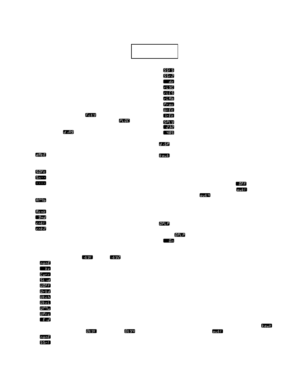
The factory prompt
appears in the lower
display and panel lockout prompt
in the
upper display. Press the increment key until
diagnosis
appears in the upper display.
Then press the MODE key.
The list below explains the menu prompts:
Date provides the date of the final control
test. The first two numbers indicate the week
(01 through 52) and the last two show the year.
Soft signifies the control software revision.
The serial number follows “Sn” in the upper
display. The six-digit number begins with
the last two digits in the upper display and
wraps around to the lower display.
Ambient temperature indicates the tem-
perature at the input 1 terminals, in degrees F.
Ambient counts is for factory use only.
Ground counts is for factory use only.
Input 1 counts is for factory use only.
Input 2 counts is for factory use only.
Depending on the modules installed and the
DIP switch settings, some of the following input
and output type displays will appear:
Types for Inputs 1
and 2
no module
thermocouple only
current detect
slidewire
universal OFF
universal RTD
universal tc high gain
universal tc low gain
universal millivolts
universal process
event input 2
Types for Outputs 1
through 4
no module
0.5A SSR
0.5A SSR w/ suppression
2.0A SSR
switched DC
form C relay
form C relay w/ suppression
form A/B Relay
process
voltage retransmit
current retransmit
power supply
RS-232 communications
EIA-485/422 communications
Display tests each display and LED. If any
display or LED is absent contact the factory.
The test output prompt can be used to
activate the available outputs on the unit, with
the exception of process outputs, transmitter
power supply or communications output. To
select an output, use the increment or decre-
ment key to advance from OFF
to the
desired output (output 1 active
through
output 4 active
). After three seconds the
corresponding load LED will light and the
output will be energized. This output will
remain energized until you select another
output or off, or exit the Diagnostic menu.
The open loop prompt enables the open-
loop error function. The error message open
loop
flashes in the lower display when ON
is selected and a heat or cool output is
full on and no temperature change has oc-
curred over a period of time, based on system
characteristics. This prompt only functions in
the proportional control mode.
Requirements:
The Diagnostics menu is a standard feature on
all Series 988 controllers. When asking the
factory for technical assistance, have the
information from the above prompts on hand.
All prompts in this menu are read only.
Sample Application:
An engineer needed to figure out why an oven
was malfunctioning. She used test output
to force ON output 1
, which controlled the
heaters. A quick check with a meter revealed a
burned out heater element.