Calibration, Filter time constant, Sensor selection – Watlow EZ-ZONE ST User Manual
Page 69
Watlow EZ-ZONE
®
ST
•
67
•
Chapter 7 Features
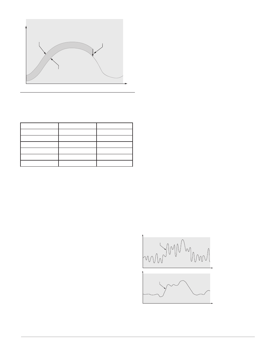
Time
Temperatur
e
Temperature Reading
from Sensor
Actual Process Temperature
Negative Calibration Offset will
compensate for the difference
between the Sensor Reading and
the Actual Temperature
Calibration
To calibrate an analog input, you will need to provide
two electrical signals or resistance loads near the ex-
tremes of the range that the application is likely to
utilize. See recommended values below:
Sensor Type
Low Source
High Source
thermocouple
0.000 mV
50.000 mV
millivolts
0.000 mV
50.000 mV
volts
0.000V
10.000V
milliamps
0.000 mA
20.000 mA
100 Ω RTD
50.00 Ω
350.00 Ω
1,000 Ω RTD
500.00 Ω
3,500.00 Ω
Follow these steps for a thermocouple or pro-
cess input:
1. Apply the low source signal to the input you are
calibrating. Measure the signal to ensure it is ac-
curate.
2. Read the value of Electrical Measurement [`Mu]
(Factory Page, Calibration Menu) for that input.
3. Calculate the offset value by subtracting this
value from the low source signal.
4. Set Electrical Input Offset [ELi;o] (Factory Page,
Calibration Menu) for this input to the offset value.
5. Check the Electrical Measurement to see whether
it now matches the signal. If it doesn’t match, ad-
just Electrical Input Offset again.
6. Apply the high source signal to the input. Mea-
sure the signal to ensure it is accurate.
7. Read the value of Electrical Measurement for
that input.
8. Calculate the gain value by dividing the low
source signal by this value.
9. Set Electrical Input Slope [ELi;S] (Factory Page,
Calibration Menu) for this input to the calculated
gain value.
10. Check the Electrical Measurement to see wheth-
er it now matches the signal. If it doesn’t match,
adjust Electrical Input Slope again.
Set Electrical Input Offset to 0 and Electrical Input
Slope to 1 to restore factory calibration.
Follow these steps for an RTD input:
1. Measure the low source resistance to ensure it is
accurate. Connect the low source resistance to the
input you are calibrating.
2. Read the value of Electrical Measurement [`Mu]
(Factory Page, Calibration Menu) for that input.
3. Calculate the offset value by subtracting this
value from the low source resistance.
4. Set Electrical Input Offset [ELi;o] (Factory Page,
Calibration Menu) for this input to the offset
value.
5. Check the Electrical Measurement to see whether
it now matches the resistance. If it doesn’t match,
adjust Electrical Offset again.
6. Measure the high source resistance to ensure it
is accurate. Connect the high source resistance to
the input.
7. Read the value of Electrical Measurement for
that input.
8. Calculate the gain value by dividing the low
source signal by this value.
9. Set Electrical Input Slope [ELi;S] (Factory Page,
Calibration Menu) for this input to the calculated
gain value.
10. Check the Electrical Measurement to see wheth-
er it now matches the signal. If it doesn’t match,
adjust Electrical Input Slope again.
Set Electrical Input Offset to 0 and Electrical Input
Slope to 1 to restore factory calibration.
Filter Time Constant
Filtering smoothes an input signal by applying a first-
order filter time constant to the signal. Filtering the
displayed value makes it easier to monitor. Filtering
the signal may improve the performance of PID con-
trol in a noisy or very dynamic system.
Adjust the filter time interval with Filter Time
[`FiL]
(Setup Page, Analog Input Menu).
Example: With a filter value of 0.5 seconds, if the
process input value instantly changes from 0 to 100 and
remained at 100, the display will indicate 100 after five
time constants of the filter value or 2.5 seconds.
Filter Time Constant
Unfiltered Input Signal
Time
Temperature
Filtered Input Signal
Time
Temperature
Sensor Selection
You need to configure the controller to match the in-
put device, which is normally a thermocouple, RTD or
process transmitter.