Output 1 solid-state relay with a contactor, Output 1 solid-state relay without a contactor, Solid-state relay derating curve – Watlow EZ-ZONE ST User Manual
Page 23: Chapter 2 install and wire
Ó
Warning:
Use National Electric (NEC)
or other country-specific
standard wiring and safety
practices when wiring and
connecting this controller to
a power source and to elec-
trical sensors or peripheral
devices . Failure to do so may
result in damage to equip-
ment and property, and/or
injury or loss of life .
NOTE: To prevent ground
loops, isolation needs to be
maintained from input to out-
put when using switched DC
or analog process outputs .
CAUTION: Always mount the
controller with the heat-sink
fins aligned vertically .
NOTE: Terminals L4 and
A1 on the limit connector
are jumpered at the factory
to complete the contactor
circuit . Additional switches
may be wired in series to the
terminals .
Ó
WARNING: If high voltage is
applied to a low-voltage con-
troller, irreversible damage
will occur .
Watlow EZ-ZONE
®
ST
•
21
•
Chapter 2 Install and Wire
Output 1 Solid-State Relay with a Contactor
–
+
–
+
–
+
S1
S2
S3
S1
S3
–
+
Thermocouple
(Input 2)
Process
0 to 20 mA
(Input 2)
N.O. (Output 3)
N.C. (Output 3)
common (Output 3)
N.O. (Output 4)
contactor (Coil 1)
Contactor
Coil 1
Contactor
Coil 2
ST_
B - _ _ _ _ - _ _ _ _ (no limit)
ST_
L - _ _ _ _ - _ _ _ _ (with limit)
common (R
UI)
T-/R- (R
UI)
T+/R+ (R
UI)
- common (Digital I/O)
+ Digital Input 6 or Output 6
+ Digital Input 5 or Output 5
ST_ _ - _ _
A _ - _ _ _ _
Remote User Interface (RUI)
common (Modb
us R
TU)
T-/R- (Modb
us R
TU)
T+/R+ (Modb
us R
TU)
- common (Digital I/O)
+ Digital Input 6 or Output 6
+ Digital Input 5 or Output 5
ST_ _ - _ _
M _ - _ _ _ _
Modbus RTU on EIA-485
Limit
Address
Selection
fuse
load
S1
S2
S3
+
–
S1
S3
2-wire
RTD
(Input 1)
3-wire
RTD
(Input 1)
Thermocouple
(Input 1)
Process
0 to 20 mA
(Input 1)
Process
0 to 10V
Î (dc)
0 to 50mV
Î (dc)
(Input 1)
N.O.
(Output 2)
common
(Output 2)
Controller
–
+
2-wire
RTD
(Input 2)
3-wire
RTD
(Input 2)
98
99
CF
CD
CE
B5
D6
D5
L2
K2
T1
S1
R1
L2
K2
T1
S1
R1
98
99
CC
C
A
CB
B5
D6
D5
1 2 3 4
ON
L3
K3
J3
A1
L4
T2
S2
R2
L2
K2
T1
S1
R1
L2
K2
T1
S1
R1
L2
K2
T1
S1
R1
L2
K2
T1
S1
R1
L3
K3
J3
A1
L4
T2
S2
R2
L3
K3
J3
A1
L4
T2
S2
R2
L3
K3
J3
A1
L4
T2
S2
R2
L3
K3
J3
A1
L4
T2
S2
R2
neutral
hot
fuse
fuse
earth
ground
1
6
3
4
A1
A2
2
5
EZ-ZONE™ ST
Patent Pending
Integrated
Control Loop
1 2
3
4
ON
LIM
IT
O
U
T 3
S
S
R
S
TA
TU
S
O
U
T 2
LIM
IT
O
U
T 3
S
S
R
S
TA
TU
S
O
U
T 2
hot
hot
Process
0 to 10V
Î (dc)
0 to 50mV
Î (dc)
(Input 2)
Power Supply
Power Supply
fuse
fuse
Output 1 (SSR)
See Quencharc note.
ST _ _ - B _ _ _ - _ _ _ _ (contactor)
Output 1 Solid-State Relay without a Contactor
-
-
+
-
+
+
-
+
-
+
1 2 3 4
ON
RTD
(Input 2)
2-wire
3-wire
Thermocouple
(Input 2)
N.O. (Output 3)
N.C. (Output 3)
common (Output 3)
N.O. (Output 4)
contactor (Coil 1)
ST_ L - _ _ _ _ - _ _ _ _
all
T-/R- (RUI)
T+/R+ (RUI)
common (RUI)
- common (Digital I/O)
+ Digital Input 6 or Output 6
+ Digital Input 5 or Output 5
ST_ _ - _ _ A _ - _ _ _ _
Remote User Interface
(RUI)
T-/R- (Modbus RTU)
T+/R+ (Modbus RTU)
common (Modbus RTU)
- common (Digital I/O)
+ Digital Input 6 or Output 6
+ Digital Input 5 or Output 5
ST_ _ - _ _ M _ - _ _ _ _
Modbus RTU on EIA-485
Limit
Power
Control
Address
Selection
load
-
S1
S2
S3
+
S1
S3
2-wire
3-wire
Thermocouple
(Input 1)
Process
0 to 20 mA
(Input 1)
Process
0 to 10V
Î (dc)
0 to 50mV
Î (dc)
(Input 1)
N.O. (Output 2)
common (Output 2)
Controller
RTD
(Input 1)
hot
neutral
fuse
98
99
CF
CD
CE
B5
D6
D5
L2
K2
T1
S1
R1
98
99
CC
CA
CB
B5
D6
D5
L2
K2
T1
S1
R1
L3
K3
J3
A1
L4
T2
S2
R2
L2
K2
T1
S1
R1
L2
K2
T1
S1
R1
L2
K2
T1
S1
R1
S1
S2
S3
L3
K3
J3
A1
L4
T2
S2
R2
L3
K3
J3
A1
L4
T2
S2
R2
S1
S3
L2
K2
T1
S1
R1
L3
K3
J3
A1
L4
T2
S2
R2
L3
K3
J3
A1
L4
T2
S2
R2
load
hot
hot
fuse
fuse
2
1
EZ-ZONE™ ST
Patent Pending
Integrated Control Loop
LIMIT
OUT 3
SSR
STATUS
OUT 2
Indicator
Lights
Process
0 to 10V
Î (dc)
0 to 50mV
Î (dc)
(Input 2)
Process
0 to 20 mA
(Input 2)
Power
Power
Power
Output 1 (SSR)
Output 1 (SSR)
See Quencharc note.
ST _ _ - A _ _ _ - _ _ _ _ (no contactor)
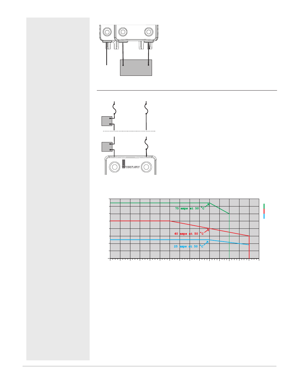
Solid-State Relay Derating Curve
0
0
35
30
25
20
15
10
5
40
45
Amps RMS
Ambient Temperatue (
o
C)
10
20
30
40
50
60
70
80
50
55
60
65
70
75 amps at 50 ºC
25 amps at 50 ºC
40 amps at 50 ºC
75
Sa
fe
Operating Area
Quencharc Note:
Switching pilot duty inductive
loads (relay coils, solenoids,
etc .) with the mechanical
relay, solid state relay or
open collector output options
requires use of an R .C . sup-
pressor .