Saving and restoring user settings, Tuning the pid parameters, Manual tuning – Watlow EZ-ZONE ST User Manual
Page 67
Watlow EZ-ZONE
®
ST
•
65
•
Chapter 7 Features
Saving and Restoring User Settings
Recording setup and operations parameter settings
for future reference is very important. If you uninten-
tionally change these, you will need to program the
correct settings back into the controller to return the
equipment to operational condition.
After you program the controller and verify proper
operation, use User Save Set [USr;S] (Setup Page,
Global Menu) to save the settings into either of two
files in a special section of memory. If the settings in
the controller are altered and you want to return the
controller to the saved values, use User Restore Set
[USr;r]
(Setup Page, Global Menu) to recall one of the
saved settings.
A digital input or the RUI Function Key can also
be configured to restore parameters.
Note:
Only perform the above procedure when you are sure that all the
correct settings are programmed into the controller . Saving he set-
tings overwrites any previously saved collection of settings . Be sure
to document all the controller settings .
Tuning the PID Parameters
Autotuning
When an autotune is performed on the EZ-ZONE
®
ST,
the set point is used to calculate the tuning set point.
For example, if the active set point is 200° and
Autotune Set Point [A;tSP] (Operations Page, Loop
Menu) is set to 90 percent, the autotune function
utilizes 180° for tuning. This is also how autotuning
works in previous Watlow controllers. In addition,
changing the active set point in previous controllers
causes the autotune function to restart; where with
the EZ-ZONE ST changing the set point after an au-
totune has been started has no affect.
A new feature in EZ-ZONE ST products will allow
set point changes while the control is autotuning, this
includes while running a profile or ramping. When
the auto tune is initially started it will use the cur-
rent set point and will disregard all set point changes
until the tuning process is complete. Once complete,
the controller will then use the new set point.
This is why it is a good idea to enter the active set
point before initiating an autotune.
Autotuning calculates the optimum heating and/or
cooling PID parameter settings based on the system's
response. Autotuning can be enabled whether or not
TUNE-TUNE+
®
is enabled. The PID settings gener-
ated by the autotune will be used until the autotune
feature is rerun, the PID values are manually adjust-
ed or TRU-TUNE+
®
is enabled.
To initiate an autotune, set Autotune Request
[`AUt]
(Operations Page, Loop Menu) to [`YES].
You should not autotune while a profile is running. If
the autotune cannot be completed in 60 minutes, the
autotune will time-out and the original settings will
take effect.
The lower display will flash between [tUnE] and
the set point while the autotun-
ing is underway. The temperature must cross the Au-
totune Set Point five times to complete the autotuning
process. Once complete, the controller controls at the
normal set point, using the new parameters.
Select a set point for the tune with Autotune Set
Point. The Autotune Set Point is expressed as a per-
cent of the Closed Loop Set Point.
If you need to adjust the tuning procedure's ag-
gressiveness, use Autotune Aggressiveness [T;Agr]
(Setup Page, Loop Menu). Select under damped [Un-
dr]
to bring the process value to the set point quickly.
Select over damped [ouer] to bring the process value
to the set point with minimal overshoot. Select criti-
cal damped [Crit] to balance a rapid response with
minimal overshoot.
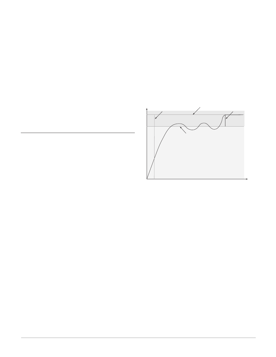
Time
Temperature
Autotune begins
Process Set Point
Autotune Set Point
(90 percent of Process Set Point)
Autotune complete
Manual Tuning
In some applications, the autotune process may not
provide PID parameters for the process characteris-
tics you desire. If that is the case, you may want to
tune the controller manually.
1. Apply power to the controller and establish a set
point typically used in your process.
2. Go to the Operations Page, Loop Menu, and set
Heat Proportional Band [`h;Pb] and/or Cool Pro-
portional Band [`C;Pb] to 5. Set Time Integral
[``ti]
to 0. Set Time Derivative [``td] to 0.
3. When the system stabilizes, watch the process
value. If it fluctuates, increase the Heat Propor-
tional Band or Cool Proportional Band value in 3
to 5° increments until it stabilizes, allowing time
for the system to settle between adjustments.
4. When the process has stabilized, watch Heat
Power [`h;Pr] or Cool Power [`C;Pr] (Operations
Page, Monitor Menu). It should be stable ±2%. At
this point, the process temperature should also be
stable, but it will have stabilized before reaching
the set point. The difference between the set point
and actual process value can be eliminated with
Integral.
5. Start with an Integral value of 6,000 and allow
10 minutes for the process temperature to reach