Scaling and calibration – Watlow CAS User Manual
Page 35
Installation
CAS User’s Guide 25
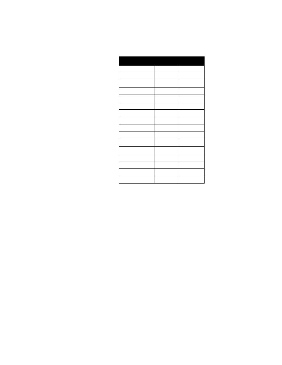
The next table shows the location of RC and RD on the analog input
board. (The analog input board is the upper board of the two-board set.)
A wire trace on the printed circuit board jumpers the RC position. When
you place a resistor in the RC position, cut the wire trace that connects
the two resistor terminals.
Scaling and Calibration
The CAS provides offset calibration for thermocouples and other fixed
ranges, and offset and span (gain) calibration for linear and pulse inputs.
(Offset and span calibration convert linear analog inputs into
engineering units using the Mx+B function.)
In order to scale linear input signals, you must:
1.
Install appropriate scaling resistors.
2.
Select the display format. The smallest possible range is
-.9999 to +3.0000; the largest possible range is -9999 to 30000.
3.
Enter the appropriate scaling values for your process.
For more information about input scaling and input offset, see Setup
Channel Inputs in Chapter 4: Setup.
Channel #
RC
RD
1
R58
R42
2
R56
R40
3
R54
R38
4
R52
R36
5
R50
R34
6
R48
R32
7
R46
R30
8
R44
R28
9
R57
R41
10
R55
R39
11
R53
R37
12
R51
R35
13
R49
R33
14
R47
R31
15
R45
R29
16
R43
R27