Cas mounting procedure, Mounting environment, Steps – Watlow CAS User Manual
Page 20
10 CAS User’s Guide
Installation
CAS Mounting Procedure
NOTE
Mount the monitor before you mount the TB-50 or do any wiring.
The monitor's placement affects placement and wiring for other
components in your system.
Mounting Environment
Install the CAS in a location free from excessive (>40 ºC) heat, dust,
and unauthorized handling. The monitor can mount in any panel
material up to 0.2" thick. (Make sure there is enough clearance for
mounting brackets and terminal blocks; the monitor extends 6.2" behind
the panel face and the screw brackets extend 0.5" above and below it.)
Steps:
1.
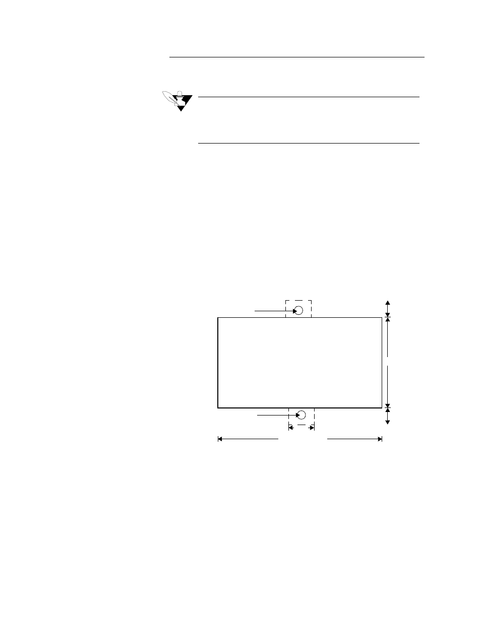
Cut a hole 3.630±0.020" long by 1.800±0.020" tall in the panel.
This figure shows the mounting hole. Cut carefully; the 0.020" (0.5
mm) tolerances don't allow much room for error. Use a punch, nib-
bler, or jigsaw, and file the edges of the hole.
2.
Insert the CAS into the hole through the front of the panel.
3.
Screw the top and bottom clips in place: insert the screw's lip into
the cutout in the metal housing just behind the front panel. Tighten
the screw.
4.
If you expect much panel vibration, use a rear support for the CAS
and its interconnecting cables.
Screw Bracket
Screw Bracket
0.375
0.375
1.800 ± 0.020
0.500
3.630 ± 0.020