Alarm output connections, Watchdog timer – Watlow CAS User Manual
Page 31
Installation
CAS User’s Guide 21
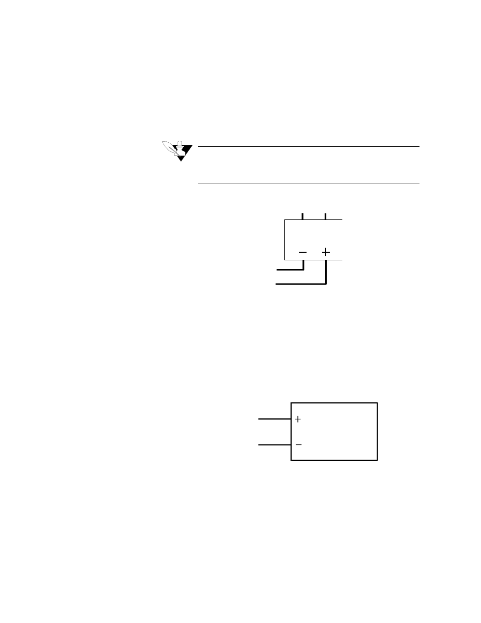
Alarm Output Connections
Typical digital outputs use external optically isolated solid-state relays
(SSRs). The SSRs use a 3 to 32 Vdc input for control, and you can size
them to switch up to 100 amps at 480 Vac. For larger currents, you can
use optically isolated relays to drive contactors.
NOTE
Digital outputs are SINK outputs. They are Low when the output is
On. Connect them to the negative side of Solid State Relays.
The figure below shows sample alarm output connections.
Watchdog Timer
The CAS watchdog timer monitors the CAS microprocessor. It is a sink
output located on TB-50 terminal #6. (Do not exceed the rating for the
watchdog timer.) Its output is Low (on) when the microprocessor is
operating; when it stops operating, the output goes High (off), which de-
energizes the SSR.
Here's the recommended circuit for the watchdog timer output:
Digital Output
+5 Vdc
SSR
SSR
+5 Vdc
(TB-50 Pin 1)
W atchdog Tim er
(TB-50 Pin 6)
- 12LS Controller (111 pages)
- 8LS Controller (140 pages)
- 8PID Controller (55 pages)
- Addendum to EZwarePlus (50 pages)
- ANASCAN (62 pages)
- ANASOFT (95 pages)
- ANAWIN 2 (154 pages)
- ANAWIN 3 (23 pages)
- Calibrating Watlow Series 988 Family Process Controls (19 pages)
- CAS200 (124 pages)
- CLS (180 pages)
- CLS200 (251 pages)
- CLS200, MLS300 and CAS200 (92 pages)
- Control Console (12 pages)
- CPC400 (230 pages)
- DIN-A-MITE Style A (9 pages)
- DIN-A-MITE Style B (14 pages)
- DIN-A-MITE Style C (22 pages)
- DIN-A-MITE Style D (9 pages)
- DIN-Mount Adapter Instruction Sheet, Rev A (1 page)
- Dual DAC (4 pages)
- EM Gateway (28 pages)
- E-Safe Hybrid Relay Rev B (4 pages)
- E-SAFE II Hybrid Power Switch (4 pages)
- EZwarePlus Programming (264 pages)
- EZ-ZONE PM (111 pages)
- EZ-ZONE PM PID (125 pages)
- EZ-ZONE PM Express Limit (34 pages)
- EZ-ZONE PM Express (35 pages)
- EZ-ZONE PM Integrated Controller (181 pages)
- EZ-ZONE RM Limit Module Rev C (127 pages)
- EZ-ZONE RMA Modul (79 pages)
- EZ-ZONE RMC (236 pages)
- EZ-ZONE RME (124 pages)
- EZ-ZONE RMH (161 pages)
- EZ-ZONE RUI/Gateway (62 pages)
- EZ-ZONE RM-Scanner-Modul (140 pages)
- EZ-ZONE ST (97 pages)
- F4 External Event Board - Rev.B (2 pages)
- HG Series Mercury Displacement Relay (6 pages)
- LogicPro (296 pages)
- Mercury Relay or MDR Retrofit (13 pages)
- MICRODIN (24 pages)
- MICRODIN (106 pages)