2 the usb cable clamp, 2 the usb cable clamp -13 – Proface FP3900 - 19 Flat Panel" User Manual
Page 122
Chapter 5 Installation and Wiring
5-13
(4)
After inserting all three pins, insert the Power Plug into the Power Connector at FP. Fix the plug with
two(2) minus screws.
5.2.2
The USB Cable Clamp
How to use the USB cable clamp
USB Cable Clamp Attachment Procedure
(1)
Insert the USB cable into the USB connector.
(2)
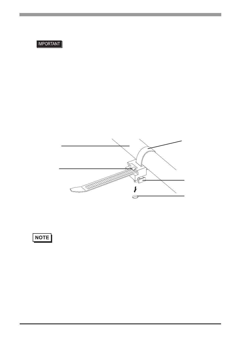
Tighten the cable clamp until the cable is secured in place and insert the convex of the clamp into the
USB fixing hole of the clamp holder on the unit to fix the clamp as shown in the following figure.
USB Cable Clamp Removal Procedure
(1)
Push up the cable clamp’s stopper with a standard flat-blade screwdriver until the clamp is unlocked.
(2)
Disconnect the USB cable.
• Confirm that all wires are connected correctly.
• The torque required to tighten these screws is 0.5 N•m - 0.6 N•m.
• To prevent the possibility of a terminal short, use a pin terminal that has an
insulating sleeve.
•
If the stopper will not move, press on (shown in figure) to free the cable clamp from
the clamp holder.
Stopper
USB Cable
USB cable clamp
USB fixing hole